What Is a ‘Valve Spool’ and How Do Spool Valves Work?
Fluid control valves rely on the opening and closing of internal passageways to direct the flow of power. But what do they look like inside, and how do these ‘valve spools’ actually work?
Most fluid control valves work by moving a mechanism inside the valve to route the fluid (air or hydraulic liquid) through the proper set of ports between the supply and the load device. The moving mechanism inside the valve is known as the ‘spool’ leading to the name for this category of control valve: the spool valve.
How Does a Spool Valve Work?
Just like electrical control switches, there are a few modular components that make up the action of a spool valve.
Figure 1. Animation of a spool valve and the components contained inside.
Most spool valves use an input power of ether electricity (solenoid valves) or mechanical motion, like a lever arm or a joystick on an excavator. This part of the valve supplies the energy required to move the internal spool, in the case of above, it's a 24 VDC solenoid coil.
The next part is the actuator and relief valve assembly, which is present if the valve is driven by a solenoid coil. The coil itself doesn’t move, so the actuator is the ferrous metal component that pushes against a spring when the coil is energized.
The valve body contains the passageways for fluid inlet and outlet, usually machined from aluminum with threaded ports to accept connectors of many sizes. The valve body is specified by the terms ‘ports’ and ‘ways.’
Finally, inside the valve body is the spool itself.
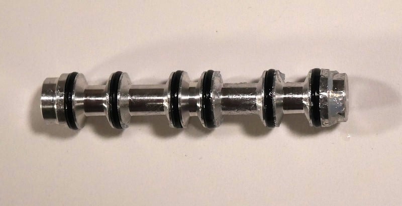
Figure 2. The valve spool mechanism is a machined shaft with grooves for o-rings. It must be greased well to maintain smooth motion.
The spool is a machined shaft with open spaces separated by lobes and o-ring seals to maintain an air-tight isolation between port openings. The spool only has two positions for most valves (2-way valves), but a sticker label on the side of the valve will show the connection between ports in both the energized and relaxed state.
There are many examples of 3-way valves, one relatable example being a common log-splitter, with positions to extend and retract the cylinder, and a central ‘neutral’ position that holds the cylinder steady.
If the valve is controlled by a solenoid, it is almost surely a 2-way valve with only energized and de-energized positions.
Where are Spool Valves Used?
These valves are common for all kinds of directional applications in both air and hydraulic systems.
There are two primary applications of 2-way valves. At its simplest, a 2-way valve with only 2 or 3 ports is most often a shut-off or on/off style valve. A 2-port valve cannot allow a reverse flow of fluid, but a 3-port valve, connected in the right direction, can allow fluid to flow to a load branch or back to a reservoir.
The other most common purpose for control valves is the actuation of cylinders. Some pneumatic cylinders are single-acting, which means that a spring returns them to a ’normal’ position. For these actuators, a 3-port valve can be sufficient. However, if the cylinder is actuated by fluid to both extend and retract, the valve must have a 5-port design, or 4-port, if the exhaust outlets are combined into one single outlet port connection.
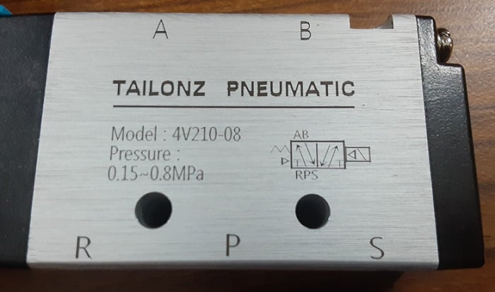
Figure 3. The symbol for a spool valve. This one shows 2 positions with 5 ports: A, B, R, P, and S.
How Do You Troubleshoot Spool Valves?
If used properly, spool valves have a very long service life, but there are a few potential danger points.
Leaking Connections
One of the most obvious to an outside observer is leaks from the connection points. Environmental factors like humidity and dissimilar metals can cause corrosion on the threaded ports leading to leakage. This becomes worse if the ports are disassembled and then reassembled without proper thread sealant.
Rust Inside the Valve
Internally, the moisture problem can be much worse. Rust can begin to form on the steel components in the supply system and within the valve itself. The rust can damage the o-rings of the spool. If fluid is able to leak around the o-rings, the cylinder cannot firmly hold its position and will droop over time. Careful dismantling and cleaning of the valve can help, along with replacing and greasing the o-rings before reassembly.
Be sure to always install proper moisture removal from a fluid system.
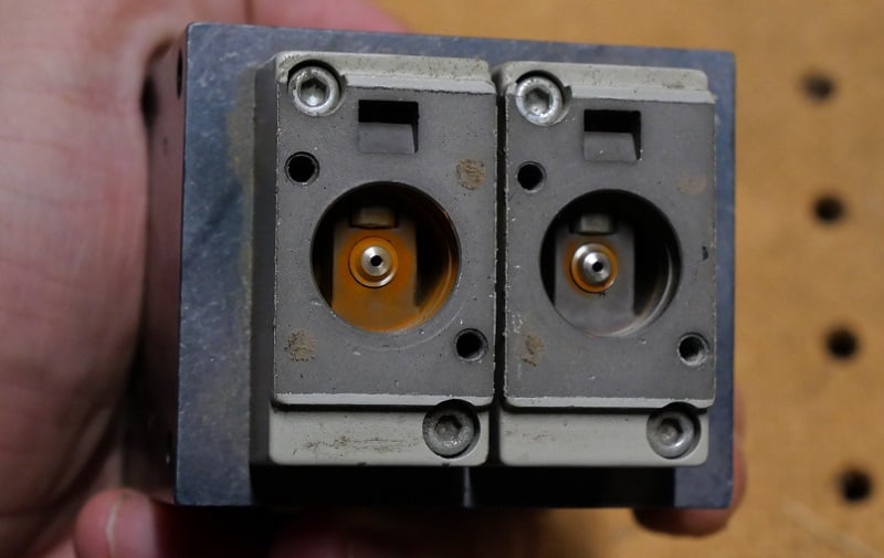
Figure 4. Rust can degrade all of the moving components inside a valve.
Particulate Damage
Somewhat related to rust, there is a chance that particulates can build up in the fluid medium. Air systems can draw in dust from the outside air, while hydraulic fluid can build up metallic debris and dirt. This can also damage the seals and the surfaces inside the valve. If the valve abrasion is too extreme, new o-rings may not solve the problem, and only valve replacement is acceptable.
Once again, filtering the fluid is extremely important!
Other Types of Valves
Since the spool valve is characterized by its on/off action and its ability to route flow in multiple directions, there are a few valves that are unsuitable as replacements.
The globe valve and gate valve, common as on/off controls, lack the speed and discrete action to serve the same purposes. Likewise, a spool valve cannot replate flow, being either always one position or the other, so a spool valve should never be used in place of a flow control (regulator) valve.
Understanding Valve Spools
It’s usually easier to visualize the flow of fluids through pipes as compared to electron motion in wires. However, it’s still a complicated field, and the knowledge of how the valves work inside can be very useful in building and maintaining automated systems.
All images used courtesy of the author


It is not uncommon to see 3 way solenoid operated valves, however there are two solenoids one at each end. When driving a cylinder this helps prevent sudden unexpected movement if power is lost, since the valve drops to its neutral position not to an active “return” position. An example of this was an access port on a vacuum chamber. It didn’t need to stop half way, so a two way valve seemed adequate until we considered the possibility of it flying open with vacuum on one side and atmosphere on the other OR flying shut with a manipulator arm passing through.
Also this type of valve is frequently piloted, the solonoids operate smaller pilot valves which then operate the cylinders that move the spool. This is important as the most common configuration I’ve encountered in pneumatics takes the air supply for the pilot valves from the centre port of the spool, which is great for systems switching clean compressed air in a textbook pneumatic cylinder drive configuration but in other usages it is nessecery to route an auxiliary air supply to the pilot valves.
Even in a simple pneumatic application it may be worth separating the pilot air supply and passing it through an extra layer of air preparation.