Facebook
 Google
 GitHub
 Linkedin
Teardown: What’s Inside a Pneumatic Solenoid Valve Bank?
Air power drives a lot of modern equipment. Robot grippers, ejectors, actuators, and rotary tables are just a few of the devices controlled by air. What’s inside those banks of solenoid valves, and how do they work?
When we think of motion in an industrial system, that usually happens as a result of one of two kinds of energy conversion, either by electrical current converted to magnetism or by the movement of a fluid. It would be hard to imagine an industrial facility without a compressed air supply. For many machines, this compressed air is distributed to dozens, or even hundreds of distinct ‘circuits’ to drive actions, each branch triggered by a solenoid valve.
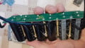
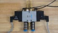
Banks of valves are often grouped together, joined either by gaskets for expansion and modularity, or fashioned as a single block of metal—robust but a bit less flexible in implementation.

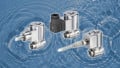
Figure 1. Two pneumatic valves are joined in a single body. Each valve in this set is a 2-way valve, with on/off control for a single pneumatic ‘circuit’.
These valve banks can experience failures, and it helps to understand the internal construction of the moving parts. We took an old valve bank and disassembled it down to the basic components to show you what’s inside, and the result of what happens if you fail to properly maintain an air system.
What is a Solenoid?
A normal solenoid valve has two separate parts: the part that uses electricity to move a component inside, and the part that uses this electrical motion to, in turn, change the flow of air.
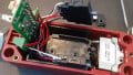
The solenoid can be removed if we wished to, perhaps, change from a 120 volt to a 24 volt control system. First, the plug is removed to troubleshoot or replace the assembly when needed. This plug has connections for (+) and (-), as well as for ground

Figure 2. The solenoid with the electrical supply plug removed.
As indicated by the printing on the side of this solenoid, it is rated for 24 VDC use, consuming 150 mA, in other words, it uses 3.6 watts of power.
In order to understand how this solenoid action influences the valve, the entire solenoid is removed from the side of the block, as shown below.

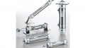
Figure 3. Solenoid with spring-loaded plunger.
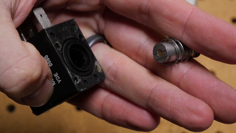
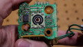
Figure 4. In this view, the plunger has been removed, clearly showing the housing which holds an inductive coil to provide motion. This coil is sealed in plastic, so it is not visible.
As you might have figured already, this plunger is far too short to pass all the way through the valve and change the flow of air on its own. That is a correct observation, but this is exactly what allows us to swap the solenoid while not removing any sensitive seals or gaskets inside the valve.
The Valve Body
Turning back to the valve, there is a lot more disassembly left to conduct.
But before removing more pieces, take a look at the two small ports that are now obvious once the solenoids are removed. When each plunger is extended by the spring, it rests against the ports, closing it. When the solenoid is energized, the plunger sinks back, opening the port.
If the air system is working, there should always be positive pressure provided to the valve. This air will pass into the portion of the valve visible here through internal passages and rest up against the small port, which is normally closed by the plunger. The moment the port is open, air may now freely flow and pressurize the rest of the valve body, which will be visible with the next component removal.
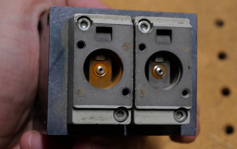
Figure 5. The point where the plunger and the valve body interact.
Once this port block is removed, the reverse side shows how the air is supplied through the small passage at the bottom. Once the plunger is retracted by the solenoid, the air pressure will be present on the metal disk just beyond that white plastic cushion.

Figure 6. Positive pressure application point when the solenoid plunger is retracted.
That metal disk is the end of the ‘spool’. This spool is the name for the moving piece inside the valve body which allows or prevents the flow of air in and out of certain ports.
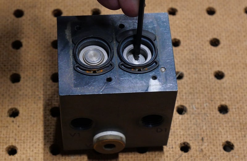
Figure 7. Demonstration of the application of force against the spool.
In many valves, an ‘exhaust’ port will allow the emptying of air from a double-acting cylinder. The way the air is routed inside the valve is the job of the spool. In the image above, I use a wrench to show the motion of the spool inside the valve. In actual operation, this force is supplied by the air pressure present in the system. In a sense, the air pressure controls the air flow, but only when the electrical signal allows it to work.

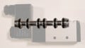
Figure 8. The spool removed from the valve.
In the manufacturing process, this single block of metal must be machined by practical processes, and the internal passages of air are anything but simple. To achieve the correct internal structure, a set of holes are drilled and tapped into the sides of the block, all interfacing with a central drilled hole. This central hole is fitted with a routing piece, with both holes for airflow and gaskets for an air-tight seal.

Figure 9. Air routing component, and it can be clearly seen which passageways are most heavily used in this valve body.
Effects of Moisture in Valves
Now that we have broken the assembly down to each of its base components, let’s return back to a couple of parts that show the effect of moisture. First, take a look back to Figures 5 and 6. Both of those pictures show clearly the rust buildup on the steel components. Now below we show the spool from that side of the valve in Figure 10.

Figure 10. The effect of moisture.
The best way to prevent rust is by installing a desiccant air drying system and properly draining it. These systems are readily available from nearly any pneumatic supplier.
The problem with moisture is that it builds up this rust which can decay the surface of the metal, clogging the small passageways and scarring the surfaces, therefore scratching the gaskets resulting in air leaks.
Properly lubricate and dry the air in the pneumatic system. It will save a lot of headache down the road.
Manual Relief Control
One final discovery about this valve takes us back to Figure 5. What if the valve was de-energized and the port was closed, but in a moment of emergency, it needed to be opened? You don’t have time to disassemble the solenoid, so you turn the manual relief control. This small screw (left side of Fig 11) turns a small cog (right side of Fig 11), pushing against the spring plunger and manually forcing air to flow and change the spool position.
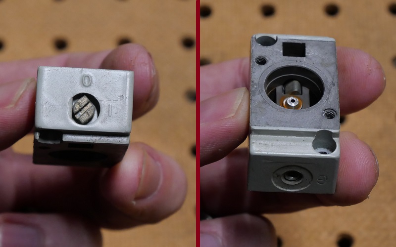
Figure 11. Top and inside view of the manual relief control screw.
Pneumatic Valve Disassembly
It’s important to look inside common components to understand how they work. If you don’t know how or why a component functions, it is very difficult to perform the proper maintenance strategies, or to design a system in a way that operates most effectively or reliably.