Facebook
 Google
 GitHub
 Linkedin
Teardown: What’s Inside a Solenoid-Controlled Safety Interlock?
Safety devices have two main purposes, both of them meant for (you guessed it) safety. They protect both machine and operator from harm. But what’s inside, and how do these switches work?
Safety is a somewhat mysterious topic in automation circles. Not that the desire for safety, or the look of the components themselves is hidden… In fact, they are usually in plain sight and clearly covered in regulations. However, rarely do we get the chance to look inside these devices and discover what sets them apart from normal switches and devices.
What makes these devices so ‘safe’ anyway?
Solenoid-Controlled Safety Switches
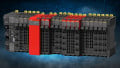
Before we dive inside the switch, let’s have a look at the outside of this particular specimen, the KLP guard interlock from IDEM.

Figure 1. The outside of the IDEM guarding interlock. Image used courtesy of the author
This safety switch is unique in several ways. First, the housing with the wiring connectors is closed with tamperproof torx (star) screws. Most automation wiring terminals, if they are covered at all, can be easily opened by depressing a small tab or button. For safety devices, the extra layer of tamperproof design ensures that it is installed and remains securely in place.
The mounting bolts are also hidden under this protective cover. The device can’t be uninstalled unless the cover is removed.
Emergency switches are also considered ‘positively operated’ which means that when energy is applied to the solenoid inside, the switch opens. Under normal operation, or under a loss of power to the switch, the lock remains firmly in place until proper operation is restored.
Circuit Connections
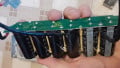
Removal of the top cover shows the wiring blocks for the power and for the signals.
There are multiple signals inside a safety switch - even more than inside standard E-stop buttons. Four of the terminals are dedicated to sensing the condition of the switch internally, both the solenoid’s position and the actual position of the lock. Two terminals provide control power to the solenoid (supplied from another safety circuit). Two other terminals provide an auxiliary monitor for the status of the lock. Finally, the last two terminals provide a selectable input, either to provide power to an indicator LED or to monitor the position of the solenoid.

Figure 2. Terminal block connectors for wiring. Image used courtesy of the author
It’s important to note that this is just one example of a safety switch wiring configuration, other models and manufacturers may provide some slight variations. However, the power supply and redundant monitoring circuits are integral to all safety lock switches.
A slightly closer examination of the terminal block numbering alongside the installation guide shows the arrangement and purpose of each terminal with the existing wires removed. By the way, for a quick review of those numbering conventions, like 11-12, 21-22, and 43-44, have a look at our article that talks about relay numbering; it’s quite interesting…

Figure 3. Terminal block and wiring diagram. Image used courtesy of the author and a modified excerpt from IDEM (click on image to view larger size)
How Does it Sense the Switch Position?
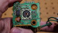
It’s good to at least understand what the switch does, and how to install it. But understanding how it actually works internally is the whole point of these teardown articles.
The next layer of the safety switch lies underneath the terminal connection board. With this PCB removed, there are two limit switches visible, tucked along each side of the housing. When I first saw this arrangement, I incorrectly assumed that these two switches were redundantly switching the same target.
In reality, one limit switch senses the position of the solenoid by means of a small plastic bracket fixed to the solenoid shaft. The other limit switch detects the movement of a spring-loaded gate which only moves when the lock mechanism is opened.

Figure 4. Dual limit switches, each with redundant contact sets. Image used courtesy of the author
In Figure 4 above, you can see the two limit switches, one removed for clearer detail. Each switch has 6 wires: 2x red, 2x black, and 2x white. These sets of wires are easily accounted in the wiring diagram. 1x set on each switch is wired in series for contact set 1 and 2 (11-12 and 21-22). The remaining pair on each switch is used as an auxiliary monitor for the state of either the locking mechanism (43-44) or the solenoid (33-34 when the switch is in the correct position).
The element of redundancy exists in the series configuration. The circuit verifies that not only is the solenoid energized, but that the lock has responded appropriately. If either mechanism sticks or fails to respond, the safety circuit will not open.
A Durable Locking Mechanism
So far, everything inside the guard lock switch makes sense, but what about the part at the end, the part that actually interacts with the latch and forms the secure bond that closes the gate?
When the four screws are removed from the end, it can be rotated so that the door latch can enter from either of 4 sides, or 4 positions at the end, each rotated by 90 degrees. In this way, there are 8x total locking position configurations available in this switch.
When the entire locking mechanism is removed, a small greased rubber dust cover prevents contaminants and moisture from getting inside the main housing.

Figure 5. Attachment of the end locking mechanism. Image used courtesy of the author
When the solenoid is energized, the rod pulls back into the housing, allowing the latch mechanism to rotate. This allows the gate latch to open and close, but only when the solenoid is energized.
If power is lost or if the solenoid is simply non-energized, the mechanical spring ensures that the solenoid remains extended and the gate latch cannot be removed.

Figure 6. Complete electrical and solenoid interaction from the terminals to the latch. Image used courtesy of the author
Looking Inside Safety Switches
Hopefully it goes without saying that if you ever run across a dismantled safety switch, its rating has been compromised and should never be used again. In my case, this was surplus equipment destined for the trash anyway, but these switches are NOT designed to be services.
According to the manual, any switch that displays mechanical or electrical damage should be replaced immediately. If not, the safety of the personnel or of the equipment could be at risk.
Now that you have seen the inside of these switches, perhaps you have a better understanding and an appreciation of how they work, and why the terminals must be wired in a certain way to maintain safety.
For more of our teardown articles, check out some of the following:
Teardown: What’s Inside a Variable Frequency Drive (VFD)?
Teardown: What’s Inside a Pneumatic Solenoid Valve Bank?
Teardown: What’s Inside a 3-Phase Induction Motor?
Teardown: What’s Inside a Timer Relay?
Teardown: What’s Inside a Human-machine Interface (HMI)?
Teardown: What’s Inside a DC Servo Motor?