Facebook
 Google
 GitHub
 Linkedin
How Does a Servo Motor Work?
We know that servo motors are found inside machines that rely on precise motion with feedback to verify proper operation, but how do they work, and what makes them different from any other kind of motor?
Let’s start this off by acknowledging that there are a lot of different types of motors in the world today. An article that discusses ‘how a motor works’ would be a terrible injustice to the wide array of incredible motion devices manufactured and used around the world.
In this article, we look inside a DC servo motor, a brushed permanent magnet motor in this case, to understand how they work, and what steps we can take to properly maintain them and ensure a long service life.

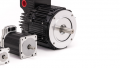
Figure 1. The view of a DC servo motor from the outside.
Outer Casing of DC Motor
Since this is a DC motor, we expect to find a marked (+) and (-) connection for voltage input. On this particular motor, the screw terminal connections are located within the neck at the top, exactly 90 degrees offset from each other. At the opposing sides sit small plastic screw covers. Hidden beneath these four locations are the secret to a brushed DC motor.
What Do Brushes Do In a DC Motor?
This secret, of course, is the brushes. In any motor, a change in the electric field (and therefore subsequent change in the magnetic field) is necessary to keep the motor rotating. If it didn’t change, then S would align with N, N would align with S, and the motor would freeze in place.
Unfortunately, this is exactly how DC electricity behaves: once it turns on, it establishes an electric field, then refuses to change until power is removed. We must have some way to change the polarity of the magnetic field at just the right rate to keep continued motion.
Introducing the brushes.

Figure 2. Removal of one brush from this brushed DC motor.
In the image above, you can see a small spring attached to what looks like a block of graphite, reminiscent of pencil lead. In fact, it is very similar. There are several compositions of brushes, but they all contain carbon. The most modern materials are a packed graphite, essentially the same as pencil lead, but mixed with metal powder to provide greater conductivity and strength.
The purpose of the carbon brushes will be explained later in the teardown, as the interaction between brush and rotor happens deep within the motor.
The reason for the spring illustrates one of the disadvantages of this motor variety. As the motor rotates, the carbon wears down, which creates a point of both friction and contaminating dust, as we will clearly see when the rotor is revealed.

Figure 3. All four carbon brushes, set 90 degrees apart, can be clearly seen.
Many brushed motors use two brushes, 180 degrees opposed. This allows electricity to enter one side of the motor, be passed to the rotor winding, then exit through the other side of the rotor.
This motor has four brushes, each spaced 90 degrees around the perimeter. Four contact points allows two windings to be equally polarized, but set on opposite sides of the rotor for a smoother rotation. Still only a single circuit is completed, just as with a two-brush motor, but now the current can pass through the rotor windings on each side in a parallel circuit.
How do Servo Motors Work?
The concept of a servo motor is really not very complicated. The difference lies in the control system. A DC motor reponds to current input and spins. Using a PWM (modulated) signal, the speed can be controlled. However, there is no method of verifying the motor’s correct operation without some sort of feedback device. It is common to attach an encoder to the motor shaft and use a PLC counter input to measure the speed and position.
The encoder is shown below (some previous damage has occurred to the encoder disk, leading to this servo’s demise).
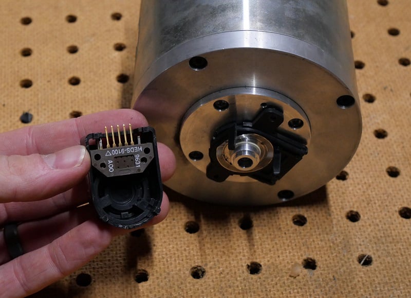
Figure 4. Encoder, shown here as two pieces, but in reality this will always be one single, very sensitive unit.
The difference between a servo and a standard motor is simply this: the servo contains a built-in encoder or similar measurement device.
Therefore a servo drive is also just a simple motor drive module but requires an input from an encoder. Since it has this feedback loop, a servo drive can also function as a stand-alone controller for even some fairly advanced motion control routines—this is virtually impossible for a simple open-loop motor driver.

Figure 5. Close-up of the encoder disk, which is damaged on this motor, but encoders will be the dedicated subject of a future teardown, as the components are quite amazing.
Rotor Covers
The next step is the removal of the end covers which house the rotor and the mechanism that interacts with the rotor.

Figure 6. Removal of back-end cover.
With the back-end cover screws removed, the cap, along with the entire rotor, is removed. The rotor can be seen clearly in the image below.
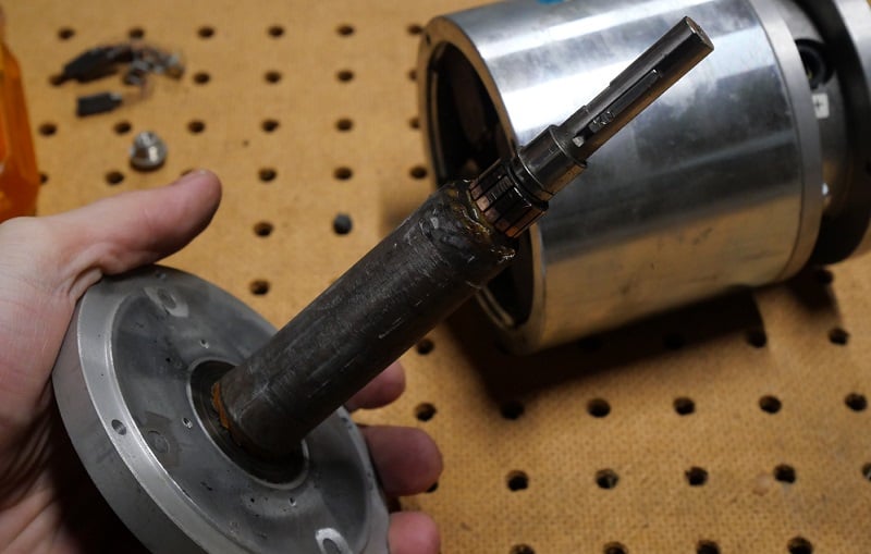
Figure 7. Rotor
This shaft is called the ‘rotor’ because it rotates, coming from the Latin roto meaning to revolve. If you look closely, you can make out a few key points on the rotor.
First, the coils are covered with an epoxy, but the copper wires of these windings can be seen at the far left end of the rotor, extending down the length under the brown epoxy until making contact with the copper pads near the right end of the rotor.
These copper pads make contact with the brushes while the motor rotates, continually changing the path of electricity, keeping perfect harmony between the speed of rotation and the speed of change for the magnetic field.
Notice the gray, dirty-looking buildup on the copper pads but only where they touch the carbon brushes. This is the friction point, the source of heat and wear.
Permanent Magnets
While the windings on the rotor accomplish the job of creating a changing magnetic field, where is the opposite end of the magnet? There must be a source of attraction and repulsion.
DC motors form these opposing magnetic fields using two different strategies: permanent magnets and field windings. In a permanent magnet motor, a set of heavy magnets provide the fixed polarity, first attracting and then repelling the rotor windings.
This motor is a permanent magnet motor, but instead of one magnet on each side, this motor has four magnets, each 90 degrees apart. This correlates to the four brushes which provide rotor windings which are also set at each 90 degree interval.

Figure 8. Permanent magnets arranged at 90 degree intervals, matching the winding offset on the rotor, enabled by the four carbon brushes.
The alternative scheme, field winding motors, use a set of wire coils to create an electromagnetic field. The same purpose but a different strategy.
Carbon Brush Contact
To understand the interaction between the brushes and the rotor, first look at Figure 9 below. We see the point at which each of the four carbon brushes, pressed continually by the spring force, would extend and make contact with the rotor.

Figure 9. Arrangement of carbon brushes in a parallel configuration, evidenced by the black wires joining opposite brush sets.
If we replace the rotor and take a careful look inside the assembly, we can see the carbon brush touching the copper pad on the rotor.

Figure 10. Carbon brush making contact with copper pad.
These copper pads are separated by insulative gaps. As the rotor revolves, the brushes will make and break contact with pads rapidly, re-directing the current to re-polarize the magnetic fields from the coils.
BEWARE: applying DC voltage to a coil will cause a large reverse voltage the moment the brush leaves the pad. This results in sparks, which can often be seen in motors with open frame cases.
This combination of dust from the brushes and sparks as the motor rotates creates a large amount of grimy buildup inside the motor, as you can see in the following image.

Figure 11. Dirt buildup from brush wear and from sparks generated by the discharge of the rotor winding coils.
How Does a Servo Motor Work?
In the end, we simply want to drive motion, but with greater accuracy and precision. Linking the motor with the feedback device into one comprehensive package does just that. Since this is a standard motor, we can expect to find servos with both AC and DC drives in both brushed and brushless DC formats.
Related Content