 Facebook
 Google
 GitHub
 Linkedin
Developing a Fuzzy Logic Controller for a Servo Motor Using Mathworks Simulink
Servo motors are widely utilized in industry for numerous applications. How do you use fuzzy logic to control a servo motor?
It is one thing to understand the concepts behind developing a fuzzy logic controller (FLC), but quite another to apply them directly to a particular control scenario.
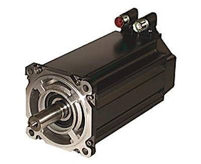
Figure 1. Servo motors such as the one shown are well-suited for fuzzy logic control. Image used courtesy of Rockwell Automation
Fuzzy logic can be used in various control scenarios, including servo motors. Servo motors are an essential part of motion control systems related to industrial automation and process control. Because of this, servo motors serve well as an example of developing an FLC.
Developing a Fuzzy Logic Controller for a Servo Motor
Unless you are experienced in writing code for implementing artificial intelligence (AI) and motor control, an excellent first step is to select a software package to assist you. Among the most popular options is Mathworks Simulink, which provide tools that can:
- integrate AI and controls together and
- perform simulations or drive actual hardware.
Some may find Mathworks Simulink easier to use than Python because of its visual approach to programming and the availability of toolboxes for both AI and controls. On the other hand, Python is suitable for those who prefer a more traditional coding approach and is far more inexpensive than Mathworks Simulink.
There is no right or wrong approach, similar to preferring ladder logic over structured text. But, for the basis of this article, we will use Mathworks Simulink. Mathworks provides a Fuzzy Logic Toolbox and a Fuzzy Logic Controller block, as illustrated in figure 2.
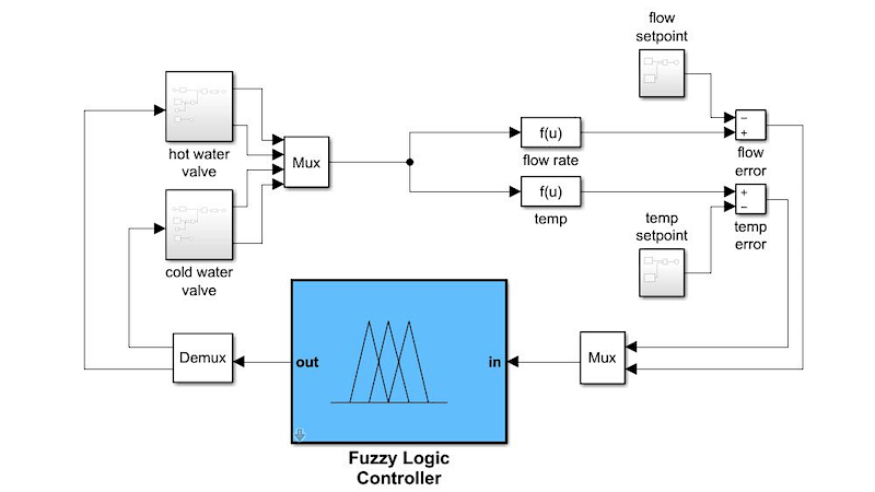
Figure 2. Mathworks Simulink supports control system development, including fuzzy logic control. Image used courtesy of Mathworks
Basic Steps to Fuzzy Logic Control
FLCs have a fuzzy logic inference system at their core, like the one shown in figure 3. The primary difference is what constitutes the inputs and outputs.
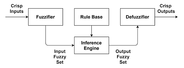
Figure 3. Basic fuzzy inference system.
The steps involved with developing an FLC for a servo motor can be summarized as follows.
- Determine inputs and output.
- Select fuzzy membership functions and linguistic identifiers for inputs and outputs.
- Assign normalization factors for the inputs to ensure their values do not exceed the membership function range.
- Generate the fuzzy rule base.
- Select a defuzzification method for the output.
- Select a fuzzy inference system (FIS).
Mapping a FIS to a Closed-loop Control System
Consider the FLC developed for the position control of a DC servo motor, developed by Manikandan and Arulmozhiya, which implemented closed-loop real-time position control.
PWM (pulse-width modulation) adjustments are typically made for servo motors based on the error between the desired position, current, or speed, and the target value. This example focuses on the error in position and the change in error obtained via an optical position sensor (encoder) on the motor’s shaft.
Determining Inputs and Outputs
Crisp error and crisp change in error form the FLC inputs. These crisp values are normalized and then enter the fuzzy logic inference engineer, where they are checked against the fuzzy rule base. After being defuzzified, the output of the fuzzy inference engine will be the PWM needed to adjust the motor position.
Fuzzy Membership Functions, Linguistic Identifiers, and Normalization
The following must be selected and configured for the position error and change in position error inputs. Figure 4 shows an example of how much of this can be accomplished through the Mathworks Fuzzy Logic Toolbox.
- Normalization factors to ensure the input to the fuzzifiers fall within the range of the fuzzy membership functions.
- Fuzzy membership functions and their configuration.
- Linguistic identifiers representing fuzzy membership.
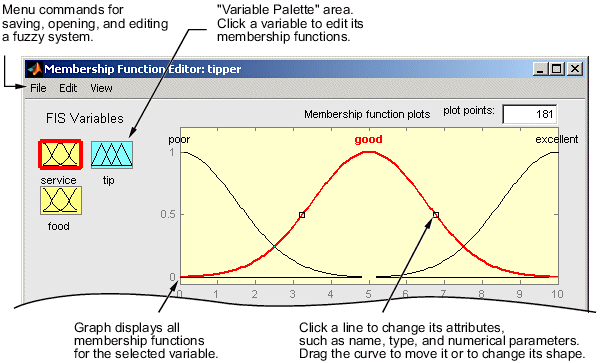
Figure 4. The Fuzzy Logic Toolbox visual membership function editor can customize membership functions for different variables (command line editors are also available). Image used courtesy of Mathworks
Except for a normalization factor, the same items must be selected and configured for the PWM output. Note that Manikandan and Arulmozhiya implemented triangular membership functions with linguistic identifiers for inputs and change in error as well as the PWM output using the same labels:
- NL -- negative little
- NM -- negative medium
- NS -- negative small
- Z -- zero
- PS -- positive small
- PM -- positive medium
- PL -- positive large
Generate Fuzzy Rule Base
The fuzzy rules, forming the fuzzy rule base, need to be developed for the controller. After being fuzzified, these rules can be extracted from existing performance data using the same inputs and outputs. Each rule will need a degree of confidence assigned.
A fuzzy rule table, such as the one shown in figure 5, can be helpful when there are a limited number of inputs and outputs. In figure 5, the two inputs are “error” and “change in error.”
The columns in the table represent the linguistic labels used for error, while the rows represent the labels used for change in error. The values in the center of the table are the fuzzy form of the PWM output.
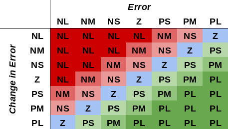
Figure 5. Example of a fuzzy rule table for servo motor control with two inputs (error and change in error) and one output (PWM).
The Matlab Fuzzy Logic Toolbox offers a fuzzy rule editor that would work well with a fuzzy rule table. In addition, rules can be visualized in two ways: (1) a 2D graphical representation of all the rules in the rule base known as the Rule Viewer, and (2) a Surface Viewer that illustrates how mapping takes place for the rule base.
Defuzzification
There are several options for defuzzification, and Matlab supports five types in their Fuzzy Logic Toolbox.
- Centroid
- Bisector
- Middle of maximum (MOM)
- Smallest of maximum (SOM)
- Largest of maximum (LOM)
The centroid method has been proven as a general-purpose defuzzifier and provides a continuous output model when there are overlapping membership functions. It is, however, not the most computationally efficient approach to defuzzification.
Other methods are available—some better adapted to closed-loop control applications due to their continuity of output and continuous controller characteristics. These include center of sums and center of maximum. The Fuzzy Logic Toolbox allows users to implement defuzzification routines; thus, these types of defuzzifiers can be used.
Keep in mind, however, that after the FIS has been built, the defuzzifier can be changed to see if another type would work better. In the Fuzzy Logic Toolbox, this is a simple matter of changing the type of defuzzifier and retesting the fuzzy control system to establish its accuracy and performance.
Fuzzy Inference Systems (FIS)
Next, the type of FIS used to map the fuzzy inputs to the fuzzy output should be selected. According to Mathworks, the Mamdani inference system is among the most widely accepted systems. Its usage is intuitive and easy for humans to interact with because of its supposed “easy-to-interpret” rule base. However, it does not typically work well for controller applications because the resulting output surface can be discontinuous.
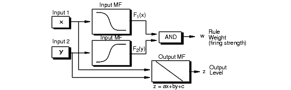
Figure 6. How the Sugeno FIS generates output. Image used courtesy of Mathworks
The Sugeno (or Takagi-Sugeno-Kang) FIS, on the other hand, is more adapted in control systems because it results in a continuous output surface and is more computationally efficient due to not using a fuzzy output membership function (illustrated in figure 6).
FLCs work well with servo motors. Such controllers are relatively straightforward to implement, primarily when used with a tool such as Matlab Simulink and its toolboxes for fuzzy logic and control systems. In a forthcoming article, we will discuss the differences between fuzzy logic and PID controllers for servo motors. Keep an eye out for it!


I see now sum of errors. When dealing with rates. like flow, there needs to be an integrator.
I have seen this problem in Fig 2 before. It can be solved with two Pi controllers. LQC can also be used but turns out to be essentially to PI controllers with the gains computed by the LQC function that minimize the ‘cost” function. Where is the FLC,s cost function. Also, fig 5 looks linear. Using linear gains is simpler.