Facebook
 Google
 GitHub
 Linkedin
The Role of Servo Drives in a Motion Control System
Servo drives and motors act as the brain and hands of motion control, but they need various tuning and programming to properly work within a control system.
The Hand and Brain of Motion Control
If you want precise motion control, you may consider a servo motor. However, a servo motor alone would do you no good without a driver to control it. Without a drive, the servo motor itself is nothing more than an industrial-grade paperweight.
Servos utilize feedback devices such as resolvers and encoders to achieve high-performance motion tasks. However, this feedback data is not useful information to the motor itself. Motors are simple machines filled with magnets and copper windings. There is no computing happening inside a motor.
Motors are like our hands; they can perform tasks, but they need a brain to tell them what and how to do it. In motion control, if servo motors are the hands of the “servo body,” then the servo drive is the brain.
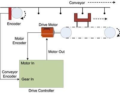
Figure 1. Schematic of electronic gearing using a drive motor.
A Simple Servo Drive
In the simplest terms, a servo drive is essentially a computer with specialized software for servo motor control. The desired output motion is programmed here.
The motor’s feedback device, which tracks its shaft position as it turns, transmits this signal to the drive for computing. The drive uses this feedback data to calculate the values used in a PID loop, such as current position and error (error being the difference between where the program wants the position to be and where the position actually is).

Figure 2. Examples of high-performance servo drives. Image used courtesy of Kollmorgen
In addition to calculating how to move the motor, a drive also needs to move the motor. To do this, the drive (which supplies power to the motor) will vary output current to the motor to induce it to rotate at a particular speed and direction.
To extend the anatomy metaphor one step further: This is the nervous system of the servo body. Once the servo brain has decided where and how to move, it fires electrical signals through its neurons (current) to command the desired motion in its hands (motor).
If a device can do these two things (think and then command) in a servo system, it qualifies as a drive. However, servo drives often come packed with many more features that make them vastly more useful, such as tuning and programming.
Servo Tuning
Once a servo system is installed, an engineer will need to tune the system before the intended process can run independently. Servo tuning refers to how well the output motion of the motor is responding to its commanded position. Is it quickly jerking toward its destination and overshooting the position, having to then backtrack to get into the correct position? Is it not overshooting its position but being so cautious about moving forward that it takes longer than desired to reach the target position? These would be examples of “underdamped” and “overdamped” tuning parameters, respectively.
Ideally, the desired position should be reached as quickly as possible with minimal overshoot. These might be “critically damped” tuning parameters with a minimized “settling time,” as depicted by the red line in Figure 3.

Figure 3. Illustration showing position error over time given different tuning parameters. Image used courtesy of Math24
Primarily, the tuning parameters in question are constants KP, KI, and KD. They affect the proportional, integral, and derivative portions of a PID loop, respectively. Tuning (choosing values for) these parameters manually is notoriously tricky.
However, modern servo drives can offer auto-tuning tools that sometimes simplify the tuning process with the click of a button, given the mechanical system is simple enough. Other times, auto-tuning tools can assist in getting close to the tuning parameters needed, but ultimately, the engineer will need to fine-tune the drive further manually.
Another option is feedforward, which can help give an extra burst or allow the engineer to develop a system model, and then leave the PID for the error remaining from the model. Other systems may use fuzzy logic, which varies parameters based on an initial set of conditions to allow the system to be in tune for longer. Additionally, systems can have cascaded PID loops controlling different components, such as one controlling velocity with the other controlling position.
A feature that can help with the tuning process is a virtual oscilloscope. This can allow an engineer to graph commanded motion, actual motion, and I/O response at a high time resolution to see how the system responds. This is a useful tool when manually tuning. A drive may even produce Bode plots, which can be useful for a system’s general maintenance.

Figure 4. Bode plot for a control system. Image used courtesy of Netnet
Given that tuning affects the integrity of the motion and can sometimes be troublesome even for experienced engineers to get right, one can see why this is an important feature in servo drives. Although any respectable servo drive will allow the user to tune the system, drives may differ in what auto-tuning features are included.
Servo Drive Programming
Drives vary in the method of programming offered. Some are programmed in one or more of the five standard IEC languages: ladder diagram (LD), function block diagram (FBD), sequential function chart (SFC), instruction list (IL), and structured text (ST). Other languages, such as basic, may be used. Proprietary programming languages are common, as seen in Figure 5, some of which are designed for ease of use for those with limited programming skills.
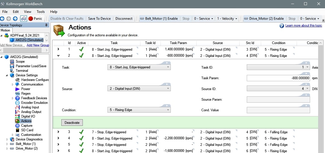
Figure 5. A screenshot of a motion control program in a Kollmorgen AKD2G drive using an action table where moves are programmed by selecting options within a dropdown list.
I/O and Safety Features in Servos
There are many other important features a drive may include. Some I/O is often built in so that the drive can react to inputs and control outputs.
For example, a sensor could initiate a motion process via a drive input, and then a green light could illuminate, indicating the process is complete via a drive output. Alternatively, these could be controlled (rather than with high/low signals from the drive’s I/O) by an external control source such as LabVIEW via a communications protocol such as EtherCAT.
This is sometimes desired in larger projects where the motion system needs to interact with a broader system’s programming, but the servo drive would need a communications option compatible with the secondary controller.
More advanced features may include the capability of driving multiple motors simultaneously, gearing or camming a secondary server motor to a client, input for an external emulated encoder to base your motion off the position of a secondary object, and safety features, including safe torque off (STO) and safe motion profiles.
It should be noted that not all drives are capable of programming any type of motion that you may imagine. Given the programming language, I/O capability, communications options, etc., methods of commanding motion may be restricted. These should be outlined and taken into account before purchasing a drive. Many product manufacturers and distributors have applications engineers on hand as a resource to help determine a suitable drive for your particular application.