 Facebook
 Google
 GitHub
 Linkedin
Common Servo Motor Feedback Devices
Learn about specific components used in feedback devices and some of the jargon you may encounter when working with servo motion systems.
A Closer Look at Feedback Devices
Part one of this series discussed why feedback devices are an integral component in a servo system. There can be some confusion about how these devices work from a technical perspective to perform this role.
This article will take a closer look at the technologies used in feedback devices to demystify these pieces of hardware and learn some of the jargon you may encounter when working with servo motion systems.
Feedback in servo systems typically comes in the form of a resolver or encoder. These are two devices that provide positional feedback of the motor’s shaft. These devices can be fitted around the motor shaft externally as the second piece of hardware in addition to the motor, or they can be internally built-in to the motor’s housing.
Types of Feedback Devices in Servo Systems
Fundamentally, resolvers and encoders do the same thing in the sense that they both will sense the position of the motor shaft so that the motor knows where it needs to go next. However, their differences can lend themselves to being more or less suited in various applications.
Resolvers
Resolvers are rugged beasts. They are analog devices that contain no onboard solid-state electronics or optics. This design makes the resolver an exceptionally robust piece of hardware that performs well in harsh environments where high temperatures, shock, vibration, radiation, and contamination may occur.
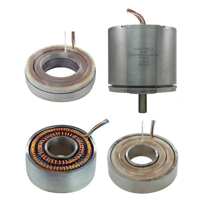
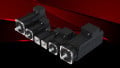
Figure 1. 3-inch series resolver with multiple housing & rotary transformer configurations. Image used courtesy of Honeywell
Resolvers are already being used in many common applications, especially in industries where these conditions tend to exist, such as oil & gas, energy, steel mills, and elsewhere.
Resolvers are cleverly engineered rotary power transformers with an output voltage that can be varied magnetically by rotating the resolver’s rotor within a stator. The multiple windings of the transformers are constructed so that with one full rotation of the resolver’s rotor, one full sine wave and one full cosine wave are generated as outputs (or multiples of these in the case of multi-speed resolvers).
Also known technically as an “analog trigonometric function generator,” resolvers aim to resolve the input vector into its sine and cosine components – where the rotor position can be found as the arctangent of these two output voltages.
An analog trigonometric function generator is a helpful term for understanding how resolvers work for those with mathematical backgrounds. However, this is not a common term for this device. Most refer to them simply as resolvers to avoid confusion.
Encoders
Encoders are considered a newer type of feedback technology that improves upon positional accuracy and precision data over resolver technology. Encoders are digital devices that often have a sensor built-in to detect the encoder’s rotor position. Several different sensor types may be used, with the two most common in my experience being optical and magnetic encoders.
Let’s consider a typical optical encoder. The basic idea is that there’s a perforated plate on the rotor with a light on one side and an optical sensor on the other.

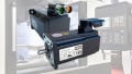
Figure 2. Components of a typical optical encoder. Image used courtesy of the Electrical Engineering and Computer Science (EECS), University of Michigan
As the rotor turns, the sensor’s output will vary from high to low as the perforations pass over it, allowing light to pass through to it. By counting the number of high and low pulses, the distance traveled can be determined.
Determining the direction the plate is turning is achieved by quadrature. The light beam is measured by two parallel sensors. The intensity of the light onto one of the sensors will increase before the other sensor.
By comparing which sensor’s output goes high first, the direction is known. These two signals are referred to as A and B channels. The inverse of these, A’ and B’, are also given dedicated channels, and their data is used as a check against transmission errors from A and B.

Figure 3. Two square waves in quadrature. The direction of rotation is indicated by the sign of the A-B phase angle which, in this case, is negative because A trails B.Image used courtesy of Sagsaw
In total, four channels are created hence the term quadrature.
Incremental Encoders
So far, we have described incremental encoders. An incremental encoder only knows how far it has traveled relative to wherever it happened to be whenever it started keeping track of this information.
When a motion control system with incremental encoders is powered down, this information is lost. Upon restarting, an incremental encoder will not “remember” where it was before. It has no natural zero position.
Because no zero position is known upon system startup, if the starting position of the target object being moved by the motor needs to be known for proper motion control, then a homing procedure must be performed. A homing procedure will move the target object with the motor until it triggers a sensor at a known point, where it can then designate that point as the “home” zero position it will use as its the ultimate point of reference. The position then becomes some positive or negative value if the motor turns left or right.
Absolute Encoders
Some applications need to always know where home is, even immediately open a system power restart. For these applications where performing a homing routine is not practical or possible, absolute encoders may be used. There are multiple types of absolute encoders that use different technologies to keep track of home even after a power restart.

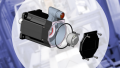
An absolute encoder. Image used courtesy of SICK AG
Some absolute encoders produce an additional Z channel in addition to channels A and B, where Z is specifically dedicated to keeping track of how many revolutions the encoder shaft is from its home position. Even if the shaft is moved while power is removed, an absolute encoder will know its position when power is restored. Due to comparatively high cost, incremental encoders are sometimes chosen over absolute ones.
Feedback is not useful information to the motor itself, however. Motors are simple machines. They are like our hands. They can perform tasks, but they need a brain to tell them what to do and how to do it. So it is not actually the motor itself doing the comparing and correcting of position data to get the motion we want – it needs a brain. For that, we will look at a piece of hardware called a servo drive in the next part of this series.


Thanks Ethan, I’m looking forward to the third part!