 Facebook
 Google
 GitHub
 Linkedin
Introduction to Basic Three-Phase Motor Control Circuits
Large motors require a circuit to turn on and off. This may be as simple as a single on/off drum-type switch or as elaborate as a VFD unit. Learn about some common control circuit designs for typical three-phase motor requirements.
Typical three-phase motors use a large amount of current at a larger voltage than most other motors. In these situations, it makes sense to design control systems that isolate the operator as far from the dangerous voltages as possible. This isolation may be in the form of a digital variable frequency drive (VFD) or soft starter, but it may even be far more basic—using relays and contactors.
Every large motor requires a circuit to turn it on and off. This may be as simple as a single on/off drum-type switch or as elaborate as a variable frequency drive unit. Regardless, a control circuit is necessary.
Full-Voltage Non-Reversing (FVNR) Motor Control
This article explains several common control circuit designs for the most typical three-phase motor requirements. If the motor needs to drive forward and reverse, or if it needs a variable speed control, then there must be a specific circuit used to drive such an application.
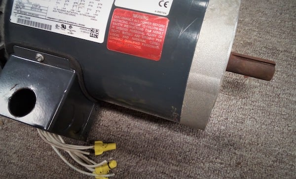
Figure 1. Driving three-phase motors requires considering both the control circuit and the power input. Fortunately, as long as safety is considered, it’s a fairly simple process.
Are you a motor troubleshooting expert? Quiz yourself with our (no pressure) worksheet!
Safety First!
Using a manual switch for direct driving of three-phase power is not recommended, except in low-voltage applications like a reversing drum switch on a milling machine or lathe. With high voltages, the opening and closing of a switch can create a spark that can injure an operator and ignite any air particulates nearby.
When designing a control circuit, it is usually better to drive it with a low voltage and then let the control circuit operate the actual power devices like contactors. If you do plan to use a direct driving manual switch, make sure that it is installed properly and operated within the proper limits.
Simple On/Off Motor Control Circuit
For this most basic application, a button turns the motor on, and another turns it off (these should probably be green and red, respectively). The buttons will drive a motor contactor with or without an overload relay.
If the motor starter contains an auxiliary (aux) contact, then the circuit can be constructed as follows:
- Both the green (NO) button and the aux contact (NO) will be connected to the control power. For a 120 vAC contactor coil, this would be the L voltage.
- Those green buttons and aux contacts will be connected together to the red (NC) button.
- That red button will connect to the contactor coil, which will return to -V or Neutral. The OL relay may be in series with the coil as well.

Figure 2. The schematic for simple motor start-stop circuit wiring.

Figure 3. Without an auxiliary contact on the starter, a relay must be used to provide the latching control. This method also works well for high-voltage motor starter coils.
In even more simple applications, a quarter-turn switch may even be sufficient. A retentive switch can produce a run/stop function, and if the switch is a spring-return to center, the control will appear as a JOG function. Either one might be useful in some situations.

Figure 4. A simple quarter-turn switch can energize the starter coil if start/stop buttons are not desired.
Full-Voltage Reversing (FVR) Motor Control
For the previous circuits, the only way to achieve a reversal of direction would be to reverse the wires for the terminals of the starter. This is inefficient and dangerous! If you need the motor to reverse, there are circuits that can do that job for you!
The concept of three-phase electricity allows you to simply interchange two of the three-phase lines into the motor. This can be accomplished using a pair of contactors or a special interlinking set of contactors, appropriately called a ‘reversing contactor.’
Although this circuit uses two contactors, it is critical that they can NEVER be energized at the same time. And if they do, by some odd chance, they should be mechanically restricted from both closing simultaneously.
In this circuit, two DPDT relays will be needed—one for the on/off control and the other to control the direction. In application, the directional control will be toggling back and forth between the starter coils.
The two relays will be energized in the same manner as the previous two circuits. Relay 1 will provide the latching ability and allow power to reach either starter coil. If this first relay is OFF, then both starters will be disabled.
The second relay is energized by a latching quarter-turn switch. When de-energized, Relay 2 will allow only Starter 2 to energize. When energized, Relay 2 will allow only Starter 1 to energize.
By this arrangement, only three combinations are possible:
- Both starters OFF
- Starter 1 only
- Starter 2 only
There is no operation of the circuit in which both starters may be energized.

Figure 5. With two relays and two interlocked starters, a simple reversing circuit may be constructed.
Using two starters to reverse direction is simple, but the arrangement can be confusing.
An example schematic is shown below. The three incoming phase lines connect to each of the input terminals of both starters. Read carefully.
- On the output side of the starters, the first pole of the first starter is connected to the third pole of the second starter.
- The second pole of both is connected.
- Finally, the third pole of the first starter is connected to the first pole of the second starter.
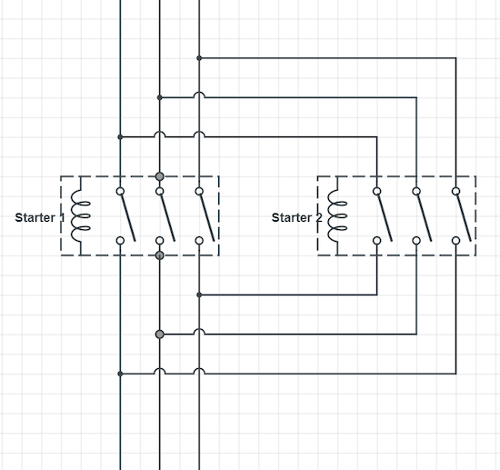
Figure 6. The arrangement of the phase lines for a reversing motor starter. The two starter coils are part of the control circuit shown before.
As you can see, if both starters were to energize at the same time, phases one through three would be shorted together and cause circuit failure. Be sure that both starters cannot energize at the same time.
Any two of the three-phase lines can be reversed in this manner. If you mix up all three lines, there will be no reversal of direction—only the potential danger of short-circuiting.
Interested in more advanced motor control circuits?
Check out the follow-up article: Introduction to Advanced Motor Control Circuits
More Articles:
- Comparing Single-Phase and Three-Phase Motors
- 3-phase Motor Types: Synchronous and Induction Motors
- Understanding Delta Wound Motors for Industrial Applications
- Brushed vs. Brushless DC Motors
- Field-oriented Control (Vector Control) for Brushless DC Motors
- Teardown: What’s Inside a 3-Phase Induction Motor?
Textbook:


Great intro. I look forward to the next in the series. Thank you.