Facebook
 Google
 GitHub
 Linkedin
Teardown: What’s Inside a Timer Relay?
PLCs and microprocessors have largely replaced timing functions in control circuits. But these timer relays still hold many necessary tasks. What’s inside these devices might be more complex than you imagined!
Back in the days before PLCs, vast walls of relays would trigger control responses, relaying signals from a source to many destinations, with timers, counters, and all other signals interwoven in complex networks of devices.
In fact, this method of ‘relaying’ a signal from one circuit to one or more destinations is the very reason why these devices get their name.
Although the standard relays are often clear and easily understood at a quick glance, the timer relays can be a bit trickier. Not only do they have more complicated internal construction, but they also have selectable settings and switches at the top. Surely, these deserve a bit closer investigation to learn what’s inside, how they work, and how can we prevent premature failure for those devices still in use today.
Check out our exclusive ebook: The Complete Guide to Relays!
Outer Case and Socket
Most industrial relays are meant to be connected to a socket with a rounded or rectangular pin layout. The rounded format is also called ‘octal’ when 8 pins are involved. There are circular bases with 10 pins as well.
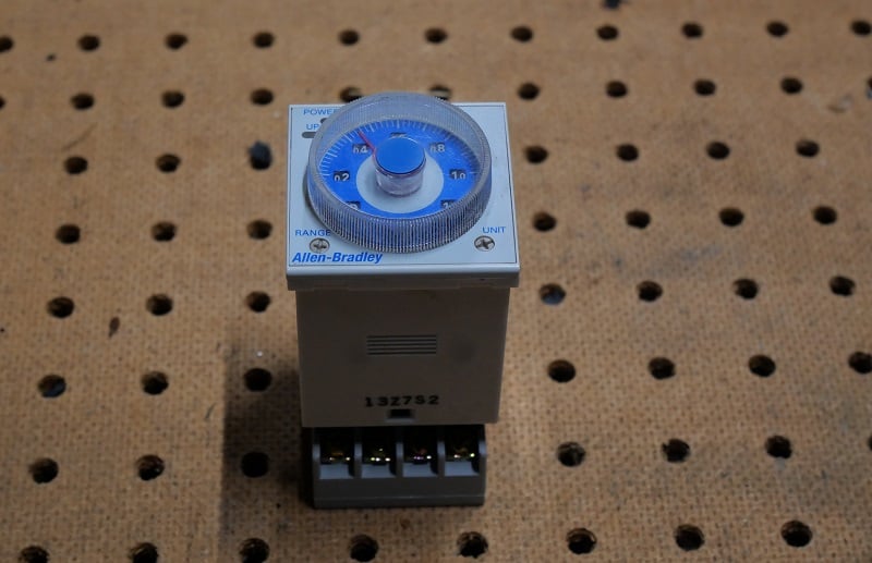
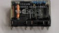
Figure 1. A timer relay on an octal socket.
This particular Allen-Bradley timer relay (model number 700-HR for those following along at home) has two sets of contacts and a single ‘coil’ input, which does not actually directly interface with the coil, as we will investigate later.
Types of Timer Relays
It should be noted here that timer relays are not a one-size-fits-all kind of device. In typical control relays, the amperage rating, number of contacts, and coil voltage can vary, but that’s about it. In other words, they all behave the same, but the electrical specs are different for varios applications.
With timer relays, we encounter more variations in function and input signal quantity, as well as the previously mentioned spec changes from typical relays.
On Delay Timer
This relay is called an ‘on-delay’ timer, meaning the timer starts the moment voltage is applied to the ‘coil’ input terminals. I say ‘coil’ in quotes because the signal is actually applied to a complex integrated circuit (IC) which, in turn, applies voltage to the coil.
Off Delay Timers
The other kind of timer is called an ‘off-delay’ which means that the voltage is applied to the coil the moment the voltage is removed from the input terminals. This kind of timer is used when you need to keep something running for a short time after a system is de-energized.
For more information on both types, see our textbook chapter discussing timers in ladder diagram PLC programming.
Inside a Timer Relay
Some of the earliest timers relied on the relationship between a resistor and capacitor to establish a charging time before voltage was applied to the coil. For more information about RC circuits, our partner site, AllAboutCircuits has an excellent textbook page with more material. However, a modern timer relay is much more complex than this.
A benefit provided by integrated circuits is the increased input resistance to the part of the circuit performing the timing and the ability to change modes with programmable functions. Some timer relays can toggle between on- and off-delay with a simple switch.
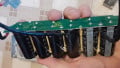
With the outer case removed, expect to see the body of the relay as normal but with far more than just a resistor and capacitor inside.

Figure 2. Inside the timer relay case.
Adjusting the Timer
The top of the relay contains a dial for the time adjustment, and two small switches for changing the time base between sec, min, and hrs, as well as the total span (range) of the dial, anywhere from a minimum total range of 1.2 seconds, up to a maximum of 300 hours. This is quite a bit of adjustment capability!
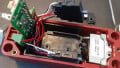
Although the dials on the face are geared together in the top cover, the admustments must interface with the ICs below. All three of the dials (main adjustment, plus range and time base) are set above brushed sliding contacts that meet at the intersection of the top cover and the main relay base.

Figure 3. Bottom side of the adjustment dials along with the top side of the main relay base.
One interesting note is a comparison of this Figure 3 with Figure 1.
The left side of Figure 3 above shows the main center dial with white plastic and three other contact pads distributed around. This relay only has two mode configuration dials around the center time adjustment, meaning that there are a few different models of top cover allowing access to more advanced functions.
Understanding Dial Adjustment Types
At the intersection of each of the dials and the main body, there is a coded set of contacts that provide information to the ICs regarding the current position. Examining the figure below, there are two distinct types of dial contact interfaces.

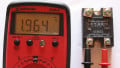
Figure 4. Adjustment dial contact pads.
In the center is the main time adjustment. This contact is a continuous (analog) dial, much like a potentiometer, common for motor speed control or volume in an analog circuit. A small, spring-loaded carbon brush slides around the center, making contact with both the inner and outer black conductive rings. As the dial rotates, the resistance changes, also changing the voltage drop, which is converted to a digital quantity indicating the current dial position.
This is not unlike a potentiometer at all, except a slight change in the wiper arrangement.
The smaller remaining pads are more complicated in nature. These are, in fact, very low-resolution absolute encoder disks. The shiny copper contact pads create a binary pattern outward from the center. As the dial is rotated by ¼ or ⅛ of a turn, a sudden change in the binary pattern indicates to the IC that a new time base or time range has been selected, and it can properly handle this new configuration.
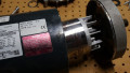
The Internal Relay
Is it redundant to say that this relay contains a relay?
It sounds odd to say, but this is the case. There is a standard DPDT relay that is energized by the logic from the IC, provided by the supply voltage.

Figure 5. Surprise, this relay contains a relay. I just had to say it…
Since the internal circuitry indirectly supplies the relay coil, it is actually far more tolerant of various voltage ranges than a typical ice cube counterpart. This relay is rated for 24-48 VAC, or 12-48 VDC, and the voltage regulation inside will ensure that the voltage reaching the coil is sufficient for operation.
Modern Timer Relays
Don’t expect to see these devices making a huge comeback in the future. As the cost per amount of capability for controllers continues to decrease, it is very inexpensive to buy timers that can be configured for nearly endless situations in very low-cost modules and programmable environments.
But these devices are still around in many control cabinets and machine centers. Understanding their internal structure can help to prevent failures and troubleshoot faults more easily and prevent future breakdowns.