 Facebook
 Google
 GitHub
 Linkedin
Pneumatic Valve Operation: Manual, Pilot, and Solenoid
Learn about various ways to activate directional control valves for fluids using manual input, air pilot sources, and electrical controls. Sometimes, valves even use a mix of multiple power sources.
Pneumatic power is an extremely common power source for industrial motion components. Most modern systems use electrical controls for the valves that perform precise timing and sequencing operations, but there are many cases when the control power still comes from sources other than digital control electronics.
The three basic methods of valve control power input come from manual (user) input, external air pilot systems, and, of course, electrical solenoid circuits. Some valves make use of a combination of these methods. The various methods are explained below.
Manual Air Control Valves
Manual input is a physical force from a user or the direct mechanical motion of the system. Pushbuttons, foot switches, and levers are the most common forms of user input, and this includes joystick control, which provides a variable flow rate, usually for hydraulic actuators. The buttons, levers, and foot switches can provide any level of control, from simple open/shut valves to 4-way operation of double-acting cylinders.
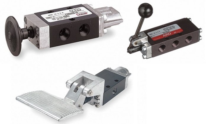
Figure 1. Pushbutton, lever, and foot switch pneumatic valves (CW from top left). Image (modified) used courtesy of ARO
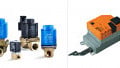
The motion of the system is often used to activate feedback devices for automatic sequencing. Since motion creates friction, these will usually have rollers with levers to minimize wear and tear. Toggle levers and rollers are common activators, just like those used in limit switches for similar electrical controls. The choice of which of these to use lies in the direction of applied motion. Levers provide contact in a single direction, while the linear rollers can provide feedback regardless of motion direction.

Figure 2. Lever and roller pneumatic switches. Image (modified) used courtesy of IMI Norgren
One manual input that is not included in a device description is the small manual pressure relief vent on solenoid valves, which acts a bit like a safety release. Most solenoid valves include a small pushbutton or switch for this additional feature.
Air Pilot Control Valves
Another non-electrical valve category uses air as the medium for performing the switching operation. A pilot valve uses a low-flow, and often low-pressure, fluid input that, when activated, will perform the switching action. It’s almost like a tiny fluid cylinder inside the valve, which, in turn, operates the much larger spool cylinder.
There are a few benefits to using air pilot operation. First, it can provide much more force than manual or solenoid operation for large valves. The force provided by the pressure of fluid can be on the order of 100s or 1000s of psi (1 to 10 MPa, although those higher values are seen only in hydraulic systems). Higher force can be necessary to move the valve spool against similar pressures in the working system.

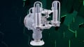
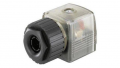
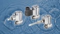
Figure 3. Air pilot valves can be identified by the air inlet ports on the ends of the valve, where the solenoid would normally be located. Image used courtesy of Clippard
Air pilot valves can also be employed to create a motion system 100% free from electrical controls. There are also pneumatic timers and logic circuit gates, so it’s entirely possible to create an advanced control system in a remote location, fed only by an air compressor.
Electronic Solenoid Valves
In the digital world of PLCs and I/O, we simply can’t fathom pneumatic systems without electrical control. Nearly every automation system that uses pneumatic motion is filled with valves that operate using the electromagnetic principle of coils and ferrous metals to energize the motion of the valve spool. This is called a ‘solenoid.’
Solenoids are usually modular, removable from the valve body, only interacting by pressing on the spring-loaded plunger when energized. The modularity allows customization for various voltages of DC and AC control system logic, the most common being 24 V DC and 120 V AC.

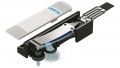
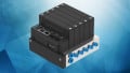
Figure 4. A single-solenoid (left) and double-solenoid valve (right). Image (modified) used courtesy of MAC Valves
The arrangement of solenoid valves allows either for a spring return, which is called a ‘single-cylinder valve,’ or it is returned to the original position by use of a second opposing solenoid, which is called a ‘double-solenoid valve’ arrangement.
The double arrangement is useful when the valve will spend nearly 50% of its service life energized. If a single solenoid were used, the valve would spend a great deal of time energized and consuming electricity. The double-solenoid model retains its position until a momentary pulse can return it to either position.
Air Piloted Solenoid Valves
One benefit of the air pilot valves is the ability to provide more force to move the spool. We may want to leverage this advantage, yet still control the valve electrically through the PLC. For this task, we rely on the solenoid valves with an air pilot operation.
The solenoid opens a small valve, allowing air to flow into the pilot chamber. The small solenoid only requires a small current and operating power, allowing the air to enter and move the main valve spool. The only disadvantage is the extra air supply line required to feed the pilot input, but this is not very difficult, since the air supply is already nearby.
So if we were to imagine perhaps the most complex pneumatic control valve, we would present to you, for your wonder and amazement: The 4-way, 5-port, air-piloted, double-solenoid directional control valve.

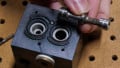
Figure 6. A 4-way, 5-port, air-piloted (the two black 1/8 inch tubes), double-solenoid valve. Image used courtesy of the author
Using Valves for Pneumatic Applications
There are three main categories of pneumatic valves: manual, air pilot, and solenoid operation.
Besides these main types, we can find many circumstances in which two of the categories are combined to leverage the advantages of each operation while still providing excellent system control.


The air piloted configuration appears relatively common, and it isn’t unusual to see directional control valves with built in piloting using air from the central input port.
Also when choosing between a single or double solenoid valve to control a pneumatic cylinder remember that in the event of loss of power the double solenoid valve will drop to a “neutral” position, whereas a single solenoid valve will dump the remaining air supply into the cylinder causing it to retract immediately.