Grid frequency unstable - potential problems?

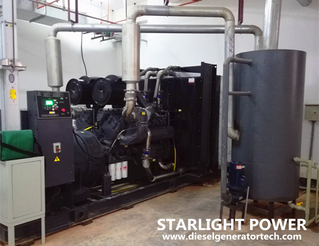
I work onboard a yacht where we have 3 pieces of 765kVA diesel gensets composed of the engine MTU 12V2000 M51A and the alternator Stamford HCM634J2. The gensets are producing 3 phase 400VAC/50Hz.

First of all, I am not sure if there is even a problem with the gensets so here goes my first question:

1. What is the allowed frequency tolerance on these type of gensets or on diesel gensets in general?

Our frequency varies less than 1%, but even that is enough to cause problem with our Main UPS and Fire detection system which are sensitive to input power quality. Because of frequency variation, UPS does an automatic bypass (just transfers input immediately to the output) and Fire detection system has a Power input quality fault. Btw, UPS' tolerance to the input power can be adjusted and it is already at the max, although I don't know what the max is because it was done 2 years ago by the service technician on some potentiometer deeeeep inside the UPS.


So...this is the situation:

When gesets are working off the grid, their frequency is super stable.
When any of them is connected to the grid, there is a frequency fluctuation.
When 2 of them are connected, fluctuation is smaller and when all 3 are connected, fluctuation is smallest, but still bigger than when they are running off the grid.

Below table shows readings when only one of the gensets was connected to the grid. So, for example, when just Centre genset was connected, genset frequency (which is in that case grid frequency as well) varies between 49.67 and 50.33 Hz, current varies fluctuates around 50A and power around 25kWA.

f, kW & A readings (Analog meters)
Port generator
Center generator
Starboard generator
Time frame measurement
Frequency on power analyzer​
49.75 to 50.15 Hz​
49.67 to 50.33 Hz​
49.63 to 50.28 Hz​
30 sec​
Ammeter readings on the main switchboard​
50 A
fluctuation​
50 A
fluctuation​
50 A
fluctuation​
18 sec​
kW readings on the main switchboard​
25 kW
fluctuation​
25-30 kW
fluctuation​
25 kW
fluctuation​
25 sec​
Voltage fluctuation on all three generators is from 400 to 402 VAC​


2. Do you have any idea what might be causing this kind of behavior?
 
Can you share a sld where we can identify ge sets and appropriated loads.... Can you develop on grid system.. What is portgenerator..

Any time !
I am sorry, but could you please explain what is an "sld". I will assume you mean a drawing of our distribution system. It is attached.

Also, what does it mean to "develop on grid system"? If you mean, to describe our on-grid system, you can check the attached drawing. If anything is unclear, please let me know.

Port is left and starboard right in ship's terms. So, we have left, centre and right genset.


Our PMS software is Cimplicity V8.2 Cim 9.
 

Attachments

Oh ok
I got the answer for SC schore connection...

Is that when connected to that point that you get Frequency drop...

Shore connection is just an option to connect to the shore grid once we are alongside. We rarely use this, so this is not our problem.

The frequency instability is constant, it only changes as I described in my 1st post.
 
Okay!

So how about KVars PF values before and during this event...
Did you perform "load balance sheet" ..system studies ..

Is that occuring at higher load ?

Unbelievable, but we don't have a Power factor meter readily available! I just learned that now! Maybe we have it somewhere in the PMS, I will have to check...

The moost comprehensive load balance sheet I found can be seen on the link below:

https://drive.google.com/file/d/1BbZxE4FP0fXSoVmghybvl6chJQwyOaVq/view?usp=sharing
 
What H&H stand for in the loab balance sheet ..
Thx for sharing again !
we may find the right solution!
But not know PF and KVARS values would be difficult to go forward....Yes you may find it at least on PMS datas ...
 
The gensets should actually work with load sharing scheme..
This is not actually well tuned.. At your yacht...
Try to search on PMS datas and post them here so we can be better support..
 
What H&H stand for in the loab balance sheet ..
Thx for sharing again !
we may find the right solution!
But not know PF and KVARS values would be difficult to go forward....Yes you may find it at least on PMS datas ...
H&H is Heinen and Hopman, it's a company doing HVAC systems.

Right now, we have one generator running - around 250kW and 25kVA, so power factor is around 0,9.
 
Maybe load sharing scheme is not tuned properly ..
Search for event trigger SOE event list alarms messages if available it should withc Cimplicity..

Also look at the block diagram for Load sharing and droop mode configuration and check if all settings are according to your installation...

You may also be able to track or get at least trend from KW/KVAR/pf/Freq signals and then troubleshooting can begin to know where that not working properly ...
Thats a small grid with 3 gensets in parallel ...

Can you check the SLD (first drawing that you shared ) it seems that it is written 2 times GENERATOR pPORTSIDE INSTEAD OF ONE OF THEM ATLEAST Would be written STANDBOARD SIDE as per you description ...
Can you confirm..

Are you able to provide Droop mode setting ...here
 
There should be a difference as you stated on your post that when islanding all is ok only when gensets are " on -grid" that you got frequency excursion so if you can provide what kind of droop curve scheme has been implemented tehn we can guide you better.
See some notes :

The so-called droop control is to select the frequency droop characteristic curve (Droop Character) similar to the traditional generator as the micro-source control method, that is, to obtain stable frequency and voltage through P/f droop control and Q/V droop control respectively. The control method separately controls the active power and reactive power of the micro-source output in the micro-grid, without the communication coordination between the gensets, realizes the goal of micro-source plug-and-play and peer-to-peer control, and ensures the unity of power balance and frequency in the micro-grid under the island, which has the characteristics of simplicity and reliability.


Using the frequency active droop characteristic (Droop Character), the unbalanced power of the system is dynamically allocated to each unit to ensure the uniformity of the frequency and voltage in the micro-grid system, which is simple and reliable. The droop control adopts voltage and current double loop control, and the current inner loop dynamic response speed is fast, which is used to improve the power quality of the inverter output. The voltage outer loop controller has a slow dynamic response speed, which can control the output voltage of the system and generate the reference signal of the inner loop.

What Is Generator Droop Control
Aug. 19, 2019
The so-called droop control is to select the frequency droop characteristic curve (Droop Character) similar to the traditional generator as the micro-source control method, that is, to obtain stable frequency and voltage through P/f droop control and Q/V droop control respectively. The control method separately controls the active power and reactive power of the micro-source output in the micro-grid, without the communication coordination between the gensets, realizes the goal of micro-source plug-and-play and peer-to-peer control, and ensures the unity of power balance and frequency in the micro-grid under the island, which has the characteristics of simplicity and reliability.

Using the frequency active droop characteristic (Droop Character), the unbalanced power of the system is dynamically allocated to each unit to ensure the uniformity of the frequency and voltage in the micro-grid system, which is simple and reliable. The droop control adopts voltage and current double loop control, and the current inner loop dynamic response speed is fast, which is used to improve the power quality of the inverter output. The voltage outer loop controller has a slow dynamic response speed, which can control the output voltage of the system and generate the reference signal of the inner loop.

The voltage-current double closed-loop control used in droop control includes voltage outer loop control and current inner loop control. Firstly, the voltage and current of the load point are collected by the measurement module, and the output instantaneous active and reactive power of the micro power supply are calculated, and then the corresponding average power is obtained through the low-pass filter LPF.

The principle is that the inverter power source detects the output power of each power, and performs independent decoupling control on the active and reactive parts. The droop characteristic is used to obtain the reference value of the output frequency and the voltage amplitude, so as to reasonably distribute the active power and reactive power of the system.

generator set

Generator Droop/Isochronous mode analysis
The ISOCH mode is the no-difference mode, but this mode is used when the generator is running, that is, set the frequency (Speed), and then the positive feedback value is adjusted by the load change to achieve a stable frequency. When two or more generators are running in parallel, if the ISOCH mode is adopted, the speed regulation ring of each generator will act when the load changes. Because each speed regulating ring is carried out separately, the speed regulation will be uneven and the adjustment will be too larger or too small, causing the generator to run off. However, if the speed regulation ring of multiple generators are connected together in the ISOCH mode, then the adjustment parameters can be corrected to achieve parallel operation of multiple generators and stable frequency operation.

Droop is a differential mode. Droop itself means drooping, that is, its speed and load curve is a drooping straight line (ISOCH mode is a parallel straight line of X-axis), and the speed control system will modify the frequency adjusted by the speed-regulating ring according to the load. The adjusted frequency, which is not the frequency we want to stabilize, but requires a secondary speed (such as manual) in order to achieve a stable frequency. The purpose of this is to prevent the generator from being overloaded or being reversed to cause a trip when the load rate of the generator set is suddenly high and low.

Two operating modes of the generator set: 1. Droop mode, the speed is sacrificed with load. 2. ISO mode, using PMS to achieve constant speed operation mode of the generator. Both Droop and ISO refer to the speed regulation characteristic mode of the governor, which is differential speed regulation and non-differential speed regulation.
 
1.2 Droop mode
Droop refers to changing the speed and frequency of the generator to proportionally change the load. That is, when the load of the generator increases, the speed or frequency is reduced by simple load feedback.

When the generator is running at full load, the Droop mode can proportionally reduce the speed of the generator. Given a suitable DRP value, the generator will always produce the same power at a fixed frequency. Therefore, the DRP mode is sometimes called the percent speed regulation mode.

If all generating sets are set to the same DRP mode, they will distribute the load correspondingly to each other. The load size depends on their speed setting. If the system load changes, the frequency of the system will also change. At this point, the speed given value will need to be changed to offset the change in feedback and return the system to its original frequency. In order for all the generators in the system to maintain the original power distribution state, each generator set needs to make the same change at the same time.

In DRP mode, when a generator set is connected to the system, the load control will not load the generator at the moment when the main circuit breaker is closed, that is to say, the generator load is set at zero. At this point, the input control point of LoadRaise must be used to make the controller load the generator. As long as the generator is operating in DRP mode, the user can increase/decrease the load of the generator at any time through the load adjustment switch.
1.3 Isochronous mode
Synchronous mode means that the generator is always running at the rated synchronous speed regardless of its power. The ISC mode has no power feedback link, so in most cases it can only be applied to the case where only one generator is running in the grid. When more than two generators are running in parallel, there must be a load feedback method to manage the load of each generator.
1.4 Load distribution in ISC mode

The EGCP-3LD can distribute the load between generators operating in multiple ISC modes. The feedback signal is provided by the LON network and the speed can be kept constant as the load changes.
The LON information is based on the rated power of the generator. If the rated capacity of each generator is different, LON will maintain their same load percentage.
The EGCP-3LS automatically adjusts the load distribution between generators operating in multiple ISC modes to maintain the output frequency at the rated value.
1.5 BaseLoad mode
The BSL mode is similar to the DRP mode and is used when running in parallel with an infinite grid or facility. The advantage is that the frequency does not change when it is separated from the facility. Simply set the trimming signal to zero to separate from the facility and return to ISC mode operation.
In BSL mode, the load reference can be changed either internally or remotely. Remote refers to the method of inputting through an external analog signal.
Share
 
Top