Facebook
 Google
 GitHub
 Linkedin
NPN and PNP Wiring | Incremental Encoders Are Not Interchangeable
Encoders rely on high-speed outputs supplying signals to a PLC. Learn why these signals cannot be interchanged at will, and some best practices for preventing false rotational counts.
When a newly installed incremental encoder suddenly begins to read backward, or drops a few counts, or refuses to register at speed, the cause is rarely the encoder itself. It is almost always the output stage meeting a controller input it was never designed for.
Encoders involve one of two output families: NPN (also known as sinking) and PNP (known as sourcing). They look identical on a block-diagram schematic, yet they behave completely differently on the wire.
This article explains the current-direction difference in physical terms, shows why a "universal" encoder is a bit of a myth, and it lists a few simple checks that stop a wrong-order from ever reaching the machine.
Understanding Encoder Channels
An incremental encoder's job is to emit three square-wave channels: A and B, which are 90° out of phase, plus the index Z, which provides one pulse per revolution. Most industrial encoders also output the complements /A, /B, /Z for noise immunity over long cable runs.
The shift in phase between A and B is what tells the controller the spin direction: if A leads B, the shaft is turning one way; if B leads A, it’s turning the other. This data is provided entirely in the timing, not in the voltage level. This is why swapping channels A and B is the classic "run backward" mistake, and why the output type matters more than people expect.
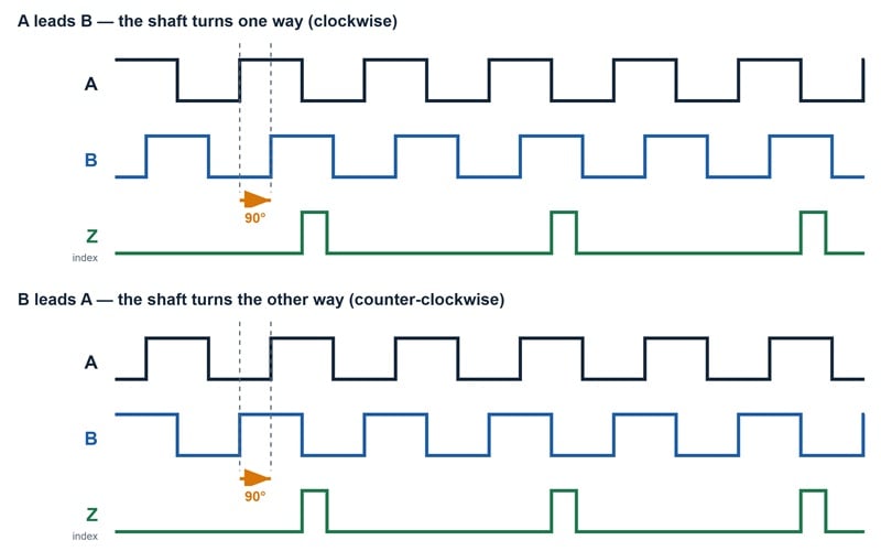
Figure 1. Square wave profiles for detecting edges. Image used courtesy of the author
Defining NPN and PNP
Both terms describe a transistor that is housed inside the encoder; they don’t refer to a voltage level. The confusion starts because both can share the same 0/+24 V rails and the same A/B/Z pins.
NPN (sinking): the transistor pulls the signal line down to 0 V when active. The load (the controller input) must pull the line up to +V through its own resistor. Current flows from the controller, through the load, into the encoder, to ground.
PNP (sourcing): the transistor pushes the signal line up to +V when active. The load must pull the line down to 0 V. Current flows from the encoder, through the load, into the controller, to ground.
The direction of current is reversed between these arrangements. A controller input built for one polarity reads the other as always-high or always-low; it never detects a transition. The encoder won’t be damaged, but the interface is mismatched.
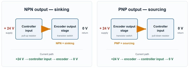
Figure 2. Current paths of NPN and PNP outputs. Image used courtesy of the author
"Universal" Encoders do Not Exist
Some encoders are sold as "NPN/PNP selectable" or "push-pull." Push-pull (also called HTL) is a genuine third output stage: it contains both a high-side and a low-side transistor, so the line can actively be driven both ways, and therefore, the encoder works with either input polarity. That is real and useful, but it is not the same as an NPN or PNP transistor component. It has a defined supply range (commonly 7-30 V or 10-30 V). A true NPN or PNP encoder has no such flexibility.
The practical rule: match the output stage to the controller input type, not to the supply voltage. A 24 V supply tells you nothing about whether the input expects a sink or a source.
Two Different Frequency Ceilings
A second, quieter cause of dropped counts at speed is the frequency ceiling (or limit), and it is specified at two different points that are easy to conflate:
- The encoder's maximum (ceiling) output frequency, which is the fastest square wave it can generate. This is limited by its internal electronics, often 100-400 kHz for incremental encoders.
- The controller's maximum (ceiling) input frequency, which is the fastest edge transition it can detect.
At a given shaft speed, the required frequency is PPR × rpm ÷ 60. A 2500 PPR encoder at 6000 rpm needs 250 kHz. If the controller input caps at 100 kHz, it will silently miss pulses long before the encoder does anything wrong. Quadrature decoding doubles the effective position resolution, but it does not raise either frequency limit; it simply uses both edges of both channels. Always check both numbers against the actual shaft speed, not the catalog maximum.
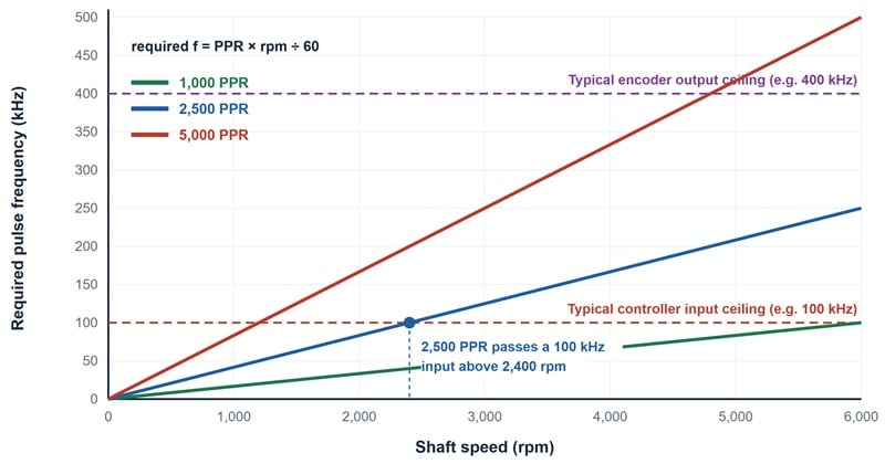
Figure 3. Controller and encoder ceiling limits. Image used courtesy of the author
Three Checks Before Placing an Order
Component selection is the first critical step to ensuring a successful test and commissioning process.
Input polarity: Read the controller manual for the encoder input: does it say "sink," "source," "NPN," "PNP," or "push-pull / HTL"? Always order the matching output. When in doubt, specify push-pull (HTL), since it is the most forgiving against either input.
Supply range: Confirm that the encoder's power supply range covers the cabinet voltage, including brown-outs. A 5 V line-driver part will not survive a 24 V rail.
Speed vs frequency: Compute PPR × max rpm ÷ 60 and confirm it sits below both the encoder output ceiling and the controller input ceiling, with margin.
Wiring Discipline Prevents Failures
Even with the right part selected and installed, there are three habits that can work together to avoid most callbacks:
- Terminate the shield at one end only (usually the controller end), to avoid ground loops that inject noise onto the A/B channels which can mimic false extra pulses.
- Keep all encoder signal cable away from VFD/motor leads. Inductive coupling is the most common source of ghost or missing counts.
- Verify the Z index separately. A missing or doubled Z causes one offset per revolution; test it at low speed before commissioning at full speed.
Bottom Line for Encoder Wiring
NPN and PNP are not two ways to say the same thing, or simple complementary voltage levels. They indicate opposite directions of current flow, and a controller built for one cannot read the other.
Always specify the output stage from the controller input, confirm the frequency ceiling at both ends, and the encoder will do exactly what its datasheet promises. For a component-level walkthrough of the A/B/Z wiring and the push-pull versus line-driver choice, see DDHL's incremental encoder wiring guide, which covers the same points from the connector outward.
Related Content