Facebook
 Google
 GitHub
 Linkedin
Commissioning IO-Link Part 2: Tutorial PLC Project
After we explored the initial configuration, it’s now time to see exactly how to implement IO-Link in a simple PLC project, explaining how to interpret process data bytes for input and output.
When installing any new type of network device, you have a relatively short time to move from initial installation to final running status. Understanding exactly how to set up and run the I/O devices in an IO-Link network can be tricky, but this article will walk through the exact steps required to get a system up and running.
Connecting IO-Link to the PLC
For this example, we will be using a Rockwell CompactLogix PLC (specifically, an L32E running with version 20 firmware). The IO-Link master is a SICK IOLG2EI, which is an Ethernet/IP IO-Link master. Finally, our IO-Link field devices include a SICK photoelectric sensor and a Balluff smart stack light.
Hardware Network Connection
The first step is to physically connect all of the devices. For this, we will need to supply power to the PLC and the IO-Link master. The master device uses threaded ⅞” connections for 24-volt power. This is fairly standard for most IO-Link masters.
The network connection to the PLC uses another threaded connector, but this one is an M12 connector with a standard RJ45 on the other end of the cable connected to the PLC. When turning on the IO-Link master, follow the steps using the buttons to set the IP address to the same subnet as your PLC.
For the two IO-Link devices, a standard M12 cable is used.

Figure 1. The system uses a Rockwell PLC, a SICK IO-Link master, and two IO-Link devices. Image used courtesy of the author
Adding IO-Link to the Project
For this Ethernet/IP device, we can add the device to the PLC in one of two ways, both of them providing the exact same functionality. 1) We can find the EDS file (usually on a download site) and install it into any PLC IDE, which includes an EDS hardware tool, or 2) We can install it as a generic Ethernet device since all of the setup details are in the datasheet.
The EDS hardware tool is a bit simpler, and that is what I have done through the RSLogix 5000 IDE. However, having also installed many generic Ethernet modules, we simply need to know the instance ID and length of the config, I, and O data, as well as the word size. From the datasheet excerpt below, we have that information (word size is SINT, which is 8 bits).
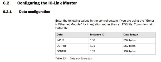
Figure 2. Configuration for creating a generic Ethernet module. Image used courtesy of SICK
Once you have added the module via the EDS file or the generic Ethernet module, set the correct IP address, give it a name (I called mine “IOLink_1”), and add it to your project.
When you download the project to the PLC, you should see the “I/O” light glowing steady green.
If the I/O light is blinking, check to see which device in the project tree is faulty with the yellow warning triangle. If it’s the IO-Link master, verify the IP address, subnet, and the cable all the way from the IO-Link to the PLC.
Configuring the I/O Ports
Once the device is added, we can access it through the controller tags. Before this becomes a truly plug-and-play performance, we need to make sure the ports are set up for either IO-Link or for standard I/O since most IO-Link masters can switch modes for some or all of the ports.
In the datasheet, we find this excerpt:
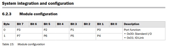
Figure 3. Configuration of individual ports. Image used courtesy of SICK
What this table tells us is that there are 8x ports, and each one can be made to act as a standard I/O port for normal sensors by assigning the value of “00” or as an IO-Link port by assigning “01.”
We find these bytes in the configuration menu of the controller tags, called something like IOLink_1:C.Data, and when this tag list is expanded, there are 194 SINTs contained inside.
The table above points us to the first two bytes numbered 0 and 1. If I wanted the first two ports to be IO-Link while the others are standard I/O, I would assign a 1 into bits 0 and 2 of the first byte or in the language of the tags: IOLink_1:C.Data[0].0 and IOLink_1:C.Data[0].2
If I wanted to make all 8x of the ports into IO-Link, I’d assign a 1 into bits 0, 2, 4, and 6 of both of the first two bytes.
Power cycle the IO-Link master to reflect the port config changes.
Reading Process Input Data
The input data is quite simple to read as long as we know where to find it. If we have assigned any of the ports to be standard I/O ports, their input data for the first four ports will be found in IOLink_1:I.Data[0], and the data for the next four ports is IOLink_1:I.Data[1].
“Why are there 16 total bits for only 8 input ports?” Good question.
As a standard I/O port, two of the pins in the M12 cable can be used for I/O data, which means that for every port, we get 2x I/O pins, giving us a total of 16.
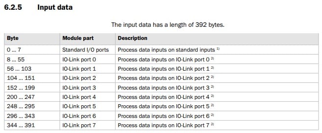
Figure 4. Input data structure. Image used courtesy of SICK
Now for the IO-Link inputs. We can read both discrete and analog data, depending on the sensor type, and we can read them both simultaneously. In my example, I have a SICK photoelectric sensor plugged into Port 0. I can see from the table that my input data will be found in bytes 8 to 55, so I expand the IOLink_1:I.Data and scroll down to Data[8] and see what I find. It appears that IOLink_1:I.Data[8].1 and IOLink_1:I.Data[8].2 show the status of Q1 and Q2 from the sensor, both in the NC (or dark-on) configuration.
I also see that in the following byte, IOLink_1:I.Data[9], the distance data is displayed as an integer. In this way, I can read both set points for boolean programming as well as the integer-based distance.
Writing Process Output Data
Writing data also requires you to understand where the bits are located, but this is more difficult because you can’t simply watch for changes and locate the data by observation.
Fortunately, the data is in a nearly identical format but with a few index changes to the start bytes.
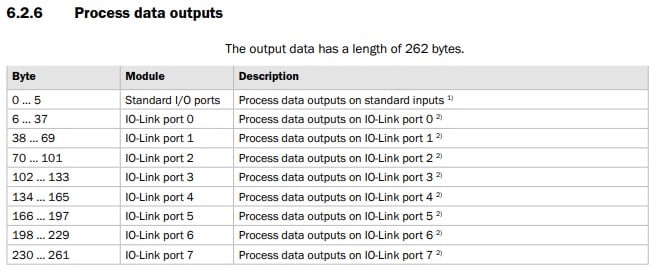
Figure 5. Output data structure. Image used courtesy of SICK
In my project, I have a Balluff stack light that can be programmed in many ways. For simplicity, I’ll run the easiest format where we’ll pick a color for the lower, middle, and top segments, so it will act just like a normal 3-tier stack light. This is called segment mode.
Since the stack light is connected to the second IO-Link port (numbered 1), I know that my output data should be written into IOLink_1:O.Data[38] and beyond. But what should I put in there?
The following datasheet excerpt shows me the contents of the first 4x bytes of data.
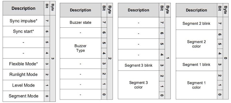
Figure 6. Contents of the first 4x bytes of the stank light output data. Image used courtesy of Balluff
First, the four bytes in question start with byte 38.
Inside IOLink_1:O.Data[38]: 01100101
This will set the Segment 1 color = 101, and the Segment 2 color = 110. These are just presets for orange and turquoise.
Inside IOLink_1:O.Data[39]: 00000100
This will set the Segment 3 color = 100, which is the preset for blue.
Inside IOLink_1:O.Data[40]: 00000000
This byte contains all zeros, as I do not wish to use any buzzer in this project.
Inside IOLink_1:O.Data[41]: 00000001
The single bit commands the light to run in segment mode and immediately, all three segments should illuminate with the selected colors.
Changing any of the colors or modes, if using a valid input range, will immediately appear on the stack light.
![Figure 7. The 4x bytes for the stack light, although the 3rd byte [40] contains all zeros, so it stays collapsed.](https://control.com/uploads/articles/iolink_programming_part_ii_7.jpg)
Figure 7. The 4x bytes for the stack light, although the 3rd byte [40] contains all zeros, so it stays collapsed. Image used courtesy of the author
With just this segment mode, you have a nearly infinite combination of colors for the stack light. All of the color selection information is stored in the PLC and transmitted to the IO-Link devices. So if the stack light needs to be replaced or the system is expanded, you simply plug in the new light and it immediately responds with whatever custom setup has been configured. There are no DIP switches in the light, and no extra software is required to configure the light. It’s all done from the PLC.
IO-Link in Remote Systems
IO-Link is providing system designers with many options while still being easy to install, like traditional I/O devices. Setting up can be a bit of a struggle, but once the system is in place, replacement and upgrading can reduce downtime to mere fractions of what was required for traditional I/O devices.