Facebook
 Google
 GitHub
 Linkedin
Control.com Asks the Experts: Serious Questions About Fluid Valves
After working with solenoid valves for many years, there are still a few questions: is AD or DC voltage better? Do we really need lubrication? I turned to an expert for some answers.
Pneumatic and hydraulic valves are everywhere, but that doesn’t mean they are simple. After working with them for many years, I still had a few deeper questions. For answers, I turned to an expert.
Mike Parzych, product marketing manager at IMI, represents a company with tremendous experience in the fluid control industry. The IMI brand leverages the combined knowledge of Norgren, Bahr, and Bimba, legendary names in the control world, and a perforce source for answers.

Control.com: Is there any difference (specifically, an advantage) to 120 VAC vs. 24 VDC controls? Is either voltage system more efficient or better for valve control?
IMI: DC voltage is generally preferred for valve operation because AC voltage can cause humming or vibration in the coil, which must be dampened with a shading or chattering ring. In terms of performance, both 24 VDC and 110/120 VAC valves function similarly, but AC designs include the shading ring to minimize noise and prevent chatter during operation.
The main advantage of 24 VDC is that it’s considered safer, with a lower risk of electric shock or arc flash. It’s also much easier to integrate into modern control systems since most PLCs and industrial controllers operate on 24 VDC, allowing direct interface with solenoid valves without the need for additional power conversion. Additionally, with higher voltage systems, current can be reduced to maintain the same magnetic field strength, but for most industrial pneumatic applications, 24 VDC remains the standard choice for simplicity and safety.
Control.com: Are manual control valves (button, lever, limit, etc.) still being placed into newly-designed installations, and if so, what applications are they?
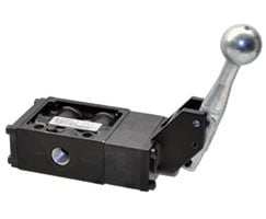
IMI: Yes, manual valves are still being used in many new installations, particularly in situations where electricity isn’t readily available or when a full electronic control system wouldn’t be justified. They’re common in emergency stop applications where a manual valve can quickly vent or exhaust downstream air pressure, as well as in hazardous locations where they provide a lower-cost alternative to hazardous-rated solenoid valves.
You’ll also find them in setups where an operator needs direct control at the point of use, like for opening a gate or door while present. When selecting or designing manual valves, the primary factors to consider are pressure, flow, and viscosity, along with temperature, material compatibility, and surface finish. While the core valve design isn’t drastically different, physical size and porting often vary to accommodate different flow requirements.
Control.com: How does the physical design of the spools for pneumatic vs. hydraulic valves differ? What factors play into the design: viscosity, pressure, flow rate, or others?
IMI: Pneumatic and hydraulic valves both serve the same basic purpose of controlling the direction and flow of a fluid, but their designs differ considerably because of the media they handle.
Hydraulic systems operate at much higher pressures and require leak-tight designs, since even small leaks can create significant messes or performance issues, while minor air leaks in pneumatic systems often go unnoticed.
There are several key differences between the two:
First is viscosity: hydraulic fluids are much more viscous and incompressible, allowing designers to use precise fits and lapped spools that do not rely on elastomeric seals.
Second is lubrication: hydraulic fluid naturally lubricates the valve internals, while pneumatic valves rely on pre-applied or air-carried lubrication, although most are assembled with enough lubricant to last their service life without maintenance.
Third is explosive decompression, which is unique to pneumatic systems, where rapid pressure loss can stress certain seal materials. In both cases, factors such as pressure, leakage, temperature, viscosity, and material compatibility must be considered to ensure proper performance and service life.
Control.com: Many sources claim that lubricators have become unnecessary for modern pneumatic systems; is this true, partially true, or false?

IMI: Lubricated air can improve valve life, provided the seal materials are compatible with the lubricant being used. Most valves are assembled with enough lubrication to last their intended service life, so in many cases, no external lubrication or maintenance is required.
Whether or not to use additional lubrication depends more on the application and installation than on the valve itself. Systems with excessive moisture in the airline can have that water wash away the internal lubrication, reducing valve life. The same can happen in systems with high levels of contamination or debris.
If the goal is to maximize cycle life, adding a lubricator can help, but it comes with one important caution: once you start lubricating, you must continue to do so. The added lubricant will wash away the factory lubrication, and if lubrication stops afterward, the valve may experience a shorter life than if it had never been lubricated at all.
Control.com: Is PID control valid for pneumatics, since air is a compressible fluid? If so, what precautions should be taken to ensure high precision?
IMI: Duty cycle and pressure work together to achieve the ideal performance from a proportional control system. Both current-controlled and voltage-controlled configurations can be used, depending on the design of the valve and control circuit. Proportional control is fully valid for pneumatic systems and is widely used across many applications, such as web tensioning, force control on pneumatic grippers in pick-and-place systems, and other processes that require variable pressure or flow.
To achieve the best precision and responsiveness, it’s recommended to use a proportional valve with a closed-loop feedback system. The feedback signal should be taken as close as possible to the point where precise pressure or flow is required. This approach allows the valve to respond more quickly and accurately to downstream demand changes, maintaining stable performance even under varying conditions.
Control.com: Is open-loop end-stop control really damaging for pneumatic cylinders, as some sources state? What protective measures are placed in open-loop cylinders to prevent that damage?
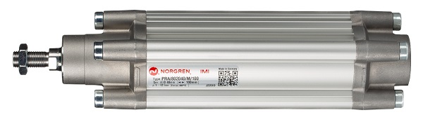
IMI: Most pneumatic cylinders are designed to operate with open-loop valves and include built-in cushioning features to prevent damage at the end of the stroke. These typically use hard mechanical cushioning disks or adjustable air cushions to absorb energy as the piston reaches the end cap. Some actuators also include active cushioning control, which automatically adjusts the exhaust flow near the end of travel to minimize impact and wear.
Allowing a cylinder to stop solely against the head or end cap without cushioning can be damaging and may create vibration that can deteriorate both the cylinder and the equipment it’s mounted on. It can also pose a hazard during startup if pressure is applied too suddenly. To manage this, many systems use soft-start valves that partially open to allow downstream pressure to rise gradually before fully opening once a preset pressure level is reached.
While a proportional valve could also be used and programmed to achieve a similar effect, using an actuator with built-in or adjustable cushions is a simpler and more cost-effective solution for most applications.
Control.com: We hear all about condition monitoring for motors, bearings, and electrical power systems. What quantities can be measured to optimize or prevent failures in fluid systems (valves, specifically), and how are those values used to make decisions?
IMI: Condition monitoring is becoming increasingly common in fluid power systems, especially for valves. Several measurable factors can be tracked to support predictive maintenance, including cycle counts, current draw, and response times. These parameters provide valuable insight into valve health and can indicate early signs of wear or performance degradation. For example, an increase in response time might suggest growing friction within the valve, which can be trended over time to predict maintenance needs before a failure occurs.
Monitoring current consumption can help detect coil or mechanical issues. In more critical applications, partial stroke testing is often used as a health check to verify valve functionality without fully cycling the process. These approaches help users plan maintenance more effectively and extend the operational life of their valves and systems.
My thanks again to Mike Parzych from IMI. Fluid control is a critical part of automation, and these insights can help provide more guidance on the design and maintenance of industrial systems.