Facebook
 Google
 GitHub
 Linkedin
Controlling Hydraulic Devices with Open and Closed Loop Systems
What if you could control the end position and the speed of a hydraulic actuator accurately with just a simple signal? Some systems use simple open/close valves, but others require far more precision.
Given our self-identified title in the digital world as ‘Control Automation’, the subject of harnessing and converting energy into motion with precise feedback and control is our wheelhouse. One of the most fascinating systems is hydraulics, where both fluid and electrical controls combine forces to move with tremendous speed and force, with impressive amounts of detail and resolution.
What's in a Hydraulic System?
A typical hydraulic system consists of a motor attached to a pump, a reservoir to hold the hydraulic fluid, and an output device such as an actuator. Most systems contain multiple output devices for one pump and motor, especially in locations where immediate access to electrical motion is difficult, or unable to provide sufficient force. The entire system is designed to return the fluid back to the reservoir after all the output devices, this is known as a closed-loop system. These systems provide a lot of power and force when designed correctly. A hydraulic system can be used to lift vehicles in the air for a mechanic to service the vehicle or to press components together on an assembly line.
The other component of a hydraulic system is the presence of control valves. Valves may not be absolutely critical in all systems, but just like buttons and switches for electricity, you are very unlikely to find a system that lacks control devices.
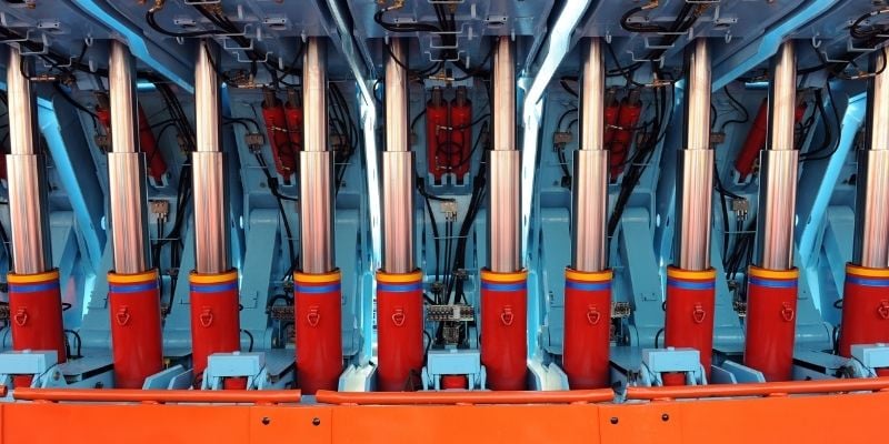
Figure 1. Hydraulic actuators are controlled by manual or electric solenoid valves. Image used courtesy of Canva
Hydraulic Cylinders or Actuators
With a typical hydraulic system, the pump will provide constant pressure to the output devices, then the fluid will be directed to either the extend or retract ports on the cylinder. When the extended port receives the pressure from the pump, fluid will fill behind the piston pushing a rod out of the top of the cylinder. If the pressure remains constant the speed of the rod will be constant, meaning if there are no flow control devices on the cylinders the rod will rapidly move and could damage equipment. Once the cylinder reaches the end of the stroke the control valve will need to switch to a center position.
Control Valves
A control valve is a block of steel with multiple ports containing internal spools which shift to direct fluid. Each stage of a control valve will have two directions through the valve to provide one action and one return, usually for a dual-acting cylinder. Typically, a control valve will have a center position that allows fluid in the cylinder to stay pressurized, but still allow the fluid coming into the valve to return to the tank.
Flow Controls
A flow control is an adjustable orifice that is placed in parallel with the fluid lines. These devices prevent rapid starting motion when pressure is applied to either the extend or retract. By reducing the flow of fluid entering the cylinder we can control the speed of the output rod, which moves the tooling.
These flow control valves are primarily responsible for finer, granular control of any hydraulic cylinder. Computer algorithms can predict motion, and then provide proper signals to speed up or slow down the cylinder motion in response to system behavior - usually in conjunction with a PID style controller.
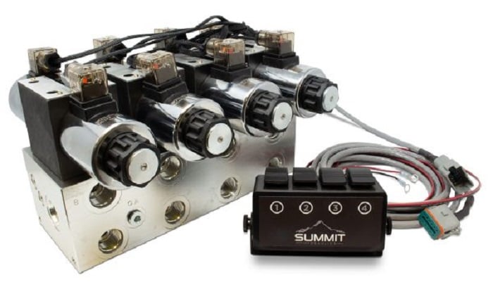
Figure 2. Solenoid-controlled spool valve bank. Image courtesy of Summit
Controlling Final Position (Open-Loop)
The simplest method of controlling the position of a hydraulic cylinder is to drive the cylinder to a hard stop. Sometimes this stop is a chunk of steel that is mounted to the fixture that holds the actuator, and sometimes the stop is within the actuator itself. This style of position control is known as an open-loop system, it gives you a clear and accurate stopping position but no feedback to the controller that the actuator has reached its stop position.
An example would be a digger, the bucket is lowered to a position using fixed pressure, and dirt is pushed from the area, the amount of earth moved is relative to the position of the bucket. In a press application, the final position may be a force sensor, pressure sensor, or position sensor, this style of positioning is known as a closed-loop system. A feedback signal is sent to the control system, signaling that the actuator has reached its target position.
The final position of the actuator is relative to the sensor that feeds back into the control system. In either case, once the actuator has reached the final position the control valve can be moved into the center position to hold the actuator's current position.
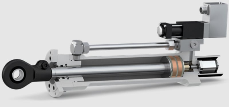
Figure 3. Internal diagram of a servo-hydraulic valve directly mounted on an actuator. Image used courtesy of Hanchen
Electrohydraulic Servo Valve (Closed-Loop)
What if you could control the end position and the speed of an actuator accurately with a simple control signal? This is where the electrohydraulic servo valve comes in. This style of valve uses a small servo to manipulate a control valve, usually proportional to the incoming voltage or current signal. Because of the precise controllability of a servo, the position of the valve can be positioned to give excellent dynamic control of the pressure and flow of fluid. If we combine a linear position sensor with this system, we now have an accurate closed-loop system that can control the final position and speed of our actuator.
Applications
Hydraulic actuators are used anywhere heavy objects need to be moved or when a large force needs to be applied to a specific location. The positioning of these actuators depends on the application. A vehicle lift may not need to have exact positioning but a pressing application may need to press components to a specific location or force. Typically bearings on a shaft will have a dimension between them so that when the shaft is installed the bearings will ride on a specific area of the journals, this requires precise positioning during the pressing process. By using an electrohydraulic servo valve with a force sensor we gather data about the pressing action and ensure that the press has completed its job successfully.
Related Content