 Facebook
 Google
 GitHub
 Linkedin
Explaining Industrial Timers: On Delay and Off Delay
Measuring time delays between equipment events predates digital control systems. What are the types of timers, and how did they work before the advent of PLCs? And how do PLCs continue the tradition?
On-delay and off-delay timers are some of the most commonly found function blocks in PLC programming, aside from those discrete on/off coils and contacts. Did you know that timers existed long before PLCs and computers were able to measure delays down the level of microseconds using their built-in oscillator components?
It’s true, and many manufacturing processes would be impossible without the ability to measure time. These days, if a machine process requires timers, it’s probably pretty inexpensive to install a small PLC. If it’s a larger system, there’s no doubt. It will certainly have digital control systems in place. But for older systems or those in a small dedicated panel for a single purpose, we are still likely to run across non-digital timers, the TON and TOF, as they are called.

Figure 1. PLC timers, or the good ol’ relay versions?
On Delay Timer, or TON
Technically, the abbreviation might better read ‘Timer On Delay’, but whatever, the main focus is the ‘on’ part of the name and the influence this has on the system.
In this setup, the timing sequence begins with a rising edge of the input control signal. If the control signal falls low, the timer will reset and wait for another rising edge to begin once again.
These statements are true for both analog (relay) timers as well as digitally programmed blocks. One of the first differences between the analog and digital versions is in the output circuit. In the PLC version, there is an input (sometimes labeled IN or EN) and an output (Q or DN). But for the analog relay with dry contacts, there is a ‘common’, an ‘NO’, and an ‘NC’ terminal to supply power to the load in the output circuit, and there is a separate input circuit to supply the control logic.
When the power to the logic input receives that rising edge input, the timer begins operating, running for the elapsed time until it reaches the preset amount. On the relay version, this is determined by a dial on the top. But on a PLC, it’s an integer attached to the function block indicating the preset time (PT or PRE).
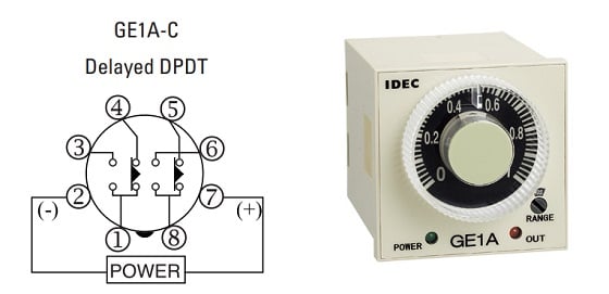
Figure 2. An on-delay DPDT timer relay with no reset function. Image (modified) used courtesy of Idec
When the timing is complete, the output contacts energize, and the NO contact is connected to the common terminal. In the PLC version, this equates to the Q output becoming ‘true’.
Those output contacts will remain energized until the control logic is removed.
A summary of the sequence in layman’s terms might go like this: When the input circuit is activated, the timing begins. As long as the input stays activated, the output turns on after a short delay. Deactivate the input to turn off the timer.
Off-Delay Timer, or TOF
The on delay timer is the easiest to understand by far. The off-delay causes confusion, especially in the case of the analog timer relay, for one main reason. At least, I was confused by one main thing until I could verify its accuracy with a relay sitting next to me.
For the most part, the operation of the TOF is opposite to the TON. Where the TON required a rising edge to begin the timing sequence, the TOF requires a falling edge of the input control. When that input is de-energized, the timing begins.
The main concern I had with this process is that for many of these timer relays, the logic input also provides 24 volt power to the coil. If I removed power to the coil, and there was no other power source, how could it keep timing for (up to) a few minutes (for some models)? At least with the TON, you had to keep supplying power the whole duration, but not in the case of a TOF.

Figure 3. An off-delay SPDT timer relay with reset function included. Image (modified) used courtesy of Omron
The example in my case is an Omron H3CR-H series off delay timer relay. The timing diagram states to supply power to the two terminals labeled ‘Source’ and the output contacts will energize. When the power is removed, the timing begins. For this model, the time duration can be up to 12 seconds. After the preset time, the relay de-energizes again.
Sure enough, even with power totally removed, the relay remains energized for the preset time. But I learned that for these types of relays, the input power signal must remain on for a minimum time to charge the relay and keep it energized after power loss. This relay only required 0.1 seconds of energized time to keep the output on for 12 seconds. Quite impressive.
The summary of the timing diagram is like this: Energize the input, and the output will also immediately energize. De-energize the input, and the timer will begin its timing cycle. At the end of the timer, the relay output de-energizes again.
Difference between Delay On and Delay Off Timers
If the two relays are still confusing, contrast the two behaviors to get a clearer understanding.
- Activate the input: the TON does not energize, the TOF does energize.
- Let the input stay on for a long time: the TON will eventually energize, the TOF just stays on.
- Deactivate the input: the TON immediately turns off, the TOF stays on for a bit.
- Let the input stay off for a long time: the TON just stays off, the TOF will eventually de-energize.
- And there they will both remain, waiting for the input to activate once again and return to step 1.
For both types of relays, some variations include a ‘reset’ input which interrupts the process at any point, de-energizing the output and requiring a return to step 1 above.
When Do I Use a TON or a TOF?
The TON is used to make one event follow another event after a preset time, like a conveyor turning on after a heater has been running for a few minutes.
The TOF, on the other hand, is used to provide a delay between two machines turning off, such as a cooling fan that must remain running for a few seconds after a motor turns off.
You’ll probably find yourself using mainly on delay timers in control programming. But on the off chance you do run across the off delay configuration, it’s nice to understand a bit about how they work.
Related Content


Why complicate a simple subject with rising this or leading that? An “ on-delay” timer starts the timing function immediately upon energization and then the contacts change state.”Off-delay” contacts change state immediately a stay changed until power is removed and the timing function is complete. “Off-dela” is seldom used.