Facebook
 Google
 GitHub
 Linkedin
LabVIEW Architecture: The State Machine
In this article, we show how to use a LabVIEW VI to program a state machine for industrial instrumentation systems.
While many different National Instruments (NI) LabVIEW architectures are available, the state machine can help most projects. The best projects to use a state machine are when a virtual instrument (VI) can be defined in a web or linear fashion, where only one particular task is operating at a specific time.
A state machine operates under the reasoning that the VI is in one of a finite number of states. These states may have names, such as “write to file” or “check temperature” or “emergency shutdown.” These states will either follow a linear progression or rely on a stimulus to jump to another state, but only one state can be executed at a time.
State Diagrams
For example, imagine a control system that must check the temperature and level for a tank system. If either of these variables is out of specification, a “fail” condition is met, and some other actions must occur before checking temperature and level again.
Rather than coding right away, one could break this into blocks, or states, that the VI could include. In this case, there needs to be an initialization step, a temperature control, a level control, a parameter check, and a fail routine. Once you define all of these states, you can interconnect using arrows to show the flow of the VI between these states. This is called a “state diagram.”

Figure 1. State diagram VI for a temperature and level controller.
Looking at figure 1’s state diagram, one can see that each state has a finite number of next possible states. From the initiation state, the VI will only lead to the temperature control state, and the temperature control state will only lead to the level control state.
Notice the diamond: the decision symbol. When the VI reaches this state, there are two possible outcomes. Either the system is running properly, and the next state is temperature control, or there was an error, and the next state is the fail routine.
State Machines in LabVIEW
The basic ingredients to build a state machine include:
- A loop
- An enumerated data type (enum) to house the state names
- A large select structure that houses the actions of each state
- A shift register that passes the next state to the state machine for the next loop iteration.
First, set up the state list with an enum constant in the block diagram and then right-click to edit the properties. In the properties menu, there is a tab called “edit items.” This is where the state names can be entered.

Figure 2. Setting up the enum with the state names.
In the block diagram, place a while loop and then a case structure, and wire them as shown in figure 3. Right-click on the case structure and click, “add case for every value.” Notice that the case structure is now populated with all cases (states) from the enum control.
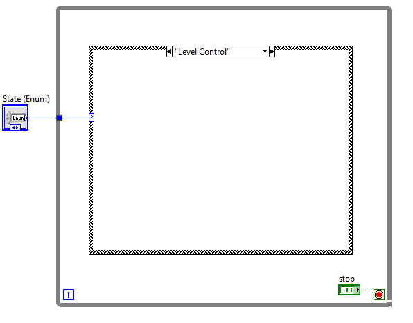
Figure 3. Beginnings of a state machine.
Next, copy the state enum and place it in every case of the case statement. This is how the next state will be determined. Wire each through the side of the case statement to the loop. Then, in each case, select the next state according to the state diagram, as shown in figure 4.

Figure 4. In the “initialize” case, the next state is “temperature control,” just like in the state diagram.
For the “fail check” case, there are two possible next states: “fail state” if there were problems or “temperature control” if there were no problems. To choose the next state, add a nested case statement, where “true” outputs the “fail state” case and “false” outputs the “temperature control” case.

Figure 5. Multiple possible outputs for the next state. In this VI, there is a button to choose which state is next; in a functioning control VI, this would be replaced with control logic.
The final step is to convert the two blue tunnels on the outside of the loop (blue squares) into shift registers. Shift registers are merely a way to access data from the previous loop iteration. This will allow the VI to see the “next state” when the loop begins again. Right-click on either tunnel and select “replace with shift register.”

Figure 6. A competed state machine, where the “fail check” state can choose between two next states, just like in the state diagram.
This is not the entire VI, but a starting point for state machine architecture. Each of these states needs to be populated by the sub-VIs that handle the measurement and control logic. Data, such as a boolean flag to indicate a problem, can be passed between loop iterations using shift registers.
Advantages of State Machine Architecture
Two major advantages in state machine architecture are documenting the code more easily and its expandability.
When troubleshooting a state machine, the programmer can always verify they are modifying the proper state. By using an enum to hold all of the states, case statements used in the state machine are already populated with the state names, instead of simply an integer that must be clearly documented elsewhere. Also, because the case structure only displays one state at a time, the entire VI is much easier to read.
State machines are also easily expandable. Each state points to the next possible states, and so the programmer only has to modify the enum, case structure, and next state for the affected states.
Suppose the temperature and level controller must now also monitor the flow rates into the tank. With many programming architectures, this is a challenge. For the state machine, however, the programmer can simply add a “flow rate control” state.
The flow rate control could go directly after the temperature control. The temperature control state will now lead into the flow rate control state, leading to the level control state. The programmer would also have to add any control logic from the flow rate control state to lead to the fail condition.
The state machine architecture is also collapsible. Suppose a new physical controller was purchased that handled flow rate and level internally, returning only a “pass/fail” signal back to LabVIEW. The programmer could simply not call each of these states individually but instead, reroute the VI flow to the failure check.
This is great for troubleshooting as well. Perhaps a “failure” signal occurs, and the programmer wants to find where without running the entire system. The programmer can bypass any state by changing the “next state” to a state that skips properly functioning states.
State machines in LabVIEW can make instrumentation systems easier to maintain, troubleshoot, expand, and document. They are not a perfect fit for every instrumentation system, but they are a powerful tool in developing automated control systems.