Facebook
 Google
 GitHub
 Linkedin
PID for Your PLC Using SP and PV. So Many Acronyms, So Little Time
Implementing PID control in a PLC is far more complicated than textbooks would make it appear. There is more to the process than simply picking gain (k) values and calculating an output value.
Control algorithms have evolved since the early days of computation. It started with simple on/off limits (like a thermostat) then moved to analog outputs with ramping and tunable output profiles, then finally arrived at modern systems, incorporating feedback and mathematical parameters into a PID loop, using historical, current, and future system values to generate a near-perfect output path.
From a user perspective, the concept sounds simple on the surface. First, pick the input variable (perhaps temperature or position), then calculate or experimentally pick the gain values for the PID terms, and finally, send the output signal to the appropriate control device (the cooling valve or the hydraulic valve unit). Sure, it sounds like only a few things to worry about.
How Do You Use PID on a PLC?
There are a number of hidden variables that the PLC programmer must understand before adding the command into a line of ladder logic. The overall concept is the same across brands, with many similarities, but a few examples will be shown later to illustrate how this might look to the end user.
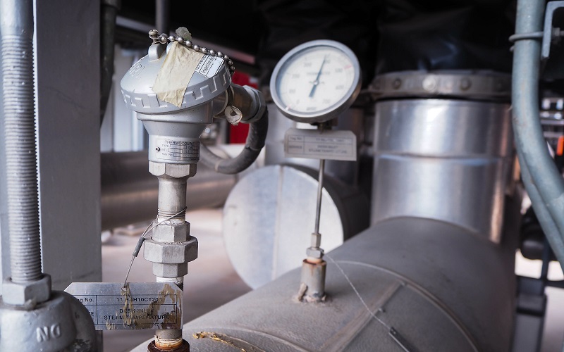
Figure 1. A common feedback device for closed-loop systems is the temperature sensor. Other examples include pressure and position. Image used courtesy of Adobe Stock
First, we must define three critical pieces of information that the PID command MUST understand.
The Process Variable or PV is the input address or the tag variable that contains the analog input information from the sensor. This may be the raw data from the input, perhaps between 0-65535 (for a 16-bit input) or less, depending on the PLC and module resolution. It may also be scaled literal values from a real-world sensor, perhaps the value being used is -100 to -50 for a temperature range, or maybe 0-350 for the mm stroke of an actuator.
The reason this data must be understood is that the PID command is likely to expect min/max limits from the programmer, if the input PV goes above or below these limits, the program will stop executing and send a fault, indicating a system error. These input limits are sometimes optional.
Likewise, the scale of data for the Output must also be understood. If the signal is directly attached to an analog output address for a proportional valve, the output min/max should relate to the resolution of the analog output, maybe the same 0-65535 range, or maybe rather in the -32,768 to 32,767 range if the output is capable of negative voltage outputs.
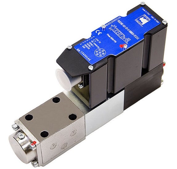
Figure 2. An example of an output device might include a servo-controlled proportional valve for precise hydraulic motion. Image used courtesy of Continental Hydraulics
PID Scaling Values
Many PLCs differentiate the concepts of a min/max used for scaling versus a min/max limit. While the scaling is used only to compute a linear slope (x input equals y output), this will NOT force an upper or lower limit on the output, it simply means that ‘minimum input equals minimum output, and maximum input equals maximum output’. An extrapolation factor.
PID Limit Values
A limit, on the other hand, is not used in the computation but is rather used to set alarms and boundaries. If the input goes above or below a limit, the system itself is out of control and may experience damage. If the output goes above or below a limit, the valve or servo may experience harsh stress and damage the final load element.
Back to the output variable; the output must be defined with both scale and limit min/max values. If the limit min/max values are set by default, they cannot both be zero, otherwise, the output will always be equal to zero, and the system will appear to be unresponsive. For temperature and flow control processes, the output is often expressed as a percentage, from 0% to 100%, relating to the 0-10v or the 4-20 mA signal to the proportional valve or PWM output.
The last of the three critical PID data values (but far from least important) is the Set Point or SP. This value must have the same unit structure as the PV. That means that if the PV is measured in temp degrees, or in mm, or in raw data, then the SP must likewise be defined. The error is the difference (subtraction) between the two data values, so you must have the same units–you can’t subtract 70 degrees from 35,682, that just doesn’t make sense. That difference may be positive or negative, that is an important detail!
Example using a Modern PLC System
What if we examine an actual example of PID implementation to learn which control values are shown by the command, as well as which items must be considered behind the scenes for proper operation?
Let me begin by saying I cannot possibly explain all elements of the tags involved with each PID command and keep the scope to one article. And indeed, if you really need to implement PID for your process, you need to read far more than just this article. However, explaining the basic I/O data and the controlling factors can be a real aid in understanding how to establish the command.
PID Command in Rockwell’s Studio 5000
Allen-Bradley ControlLogix and CompactLogix
When you drag a PID function block onto a ladder rung, the function will execute as long as the rung is true according to a regularly updated timer. If you wish to have control over the time delay for PID updates, the tag is PID_Name.UPT with a base of milliseconds.
PID_Name is whatever name you assign to the PID type tag created in your controller or program scope tag listing.
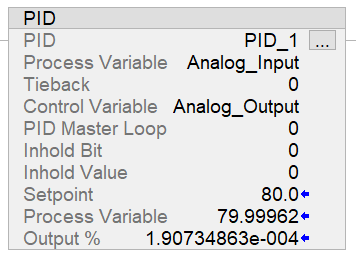
Figure 3. PID command in Studio 5000.
In my case, I have created PID_1 with fictitious tags called ‘analog input’ and ‘analog output’ to represent the PV and output (CV). If you have a real analog I/O module, simply use the analog values from these modules. Both of these tags are REAL data types.
I set the PID function to update every 10 ms (meaning that the PID_1.UPT tag = 0.01).
The scaling values are determined by default when the function is downloaded to the controller, but you can adjust the tags or open the tuning/configuration menu by clicking the three dots in the upper-right corner of the PID function block.
To observe the change in this PID function, you can adjust either the SP or the PV to simulate a real-world situation.
As you can see from this example, the SP is 80, the PV is so close that the SP that the output is reduced to a very tiny percentage. Note: I excluded Ki (integral gain) from this loop to stabilize the output for getting a screenshot, so the PV will never actually reach the SP exactly.
How Does the Scaling Affect the Output?
For a simulated scenario, you can adjust the scale of the output and input however you wish, since it’s not connected to an actual responsive device. But remember this: if you link the Control Variable to a real analog output, you must establish a max and min scale that will send the proper value to the analog output tag.
For example, if you are using a ControlLogix 1756-OF4, with 4x voltage outputs, the resolution is 15 bits over 0-10 volts. This means that your minimum scale should be 0, and the max scale should be 32,767 (2^15-1).
Alternatively, if you are using the current output on this module for a 0-20 mA output, this is rated for 16 bits. So, in this case, the min scale output should be -32,768 (-2^15) while the max scale output remains at 32,767 (2^15-1).
These details for this specific module come from pages 183-184 of the user manual. Please do not rely on these numbers for all situations.
Most output modules can adapt to devices with 0-10 volt, 0-5 volt, -10 to 10 volt, -20 mA, and 4-20 mA just with some configuration and wiring details, so make sure your output scale matches the type of signal you wish to send.
Although it may be impossible to provide an entire scope of coverage for PID controls and programming in one article, it can be helpful to understand the basic functions, then learn how to set them up in a simulated environment to be sure they will respond as accurately as possible to minimize the chance of downtime and failures when the real system is created.
Related Content