 Facebook
 Google
 GitHub
 Linkedin
Tutorial: Using a Beckhoff IPC for Timing and Counting
Timers and counters are two of the most important fundamental function blocks in automation programming. Learn how to use TwinCAT 3 to program and monitor these important function variables.
In previous Beckhoff TwinCAT tutorials, we have covered digital I/O while setting up a basic program (part 1) then we established analog signal manipulation with basic math commands (part 2). Now, it’s time to move away from the purely physical world and investigate variables and function blocks that exist inside the controller’s memory. In this article, we’ll investigate the timer and counter functions with basic examples for each one.
Background on PLC Timers
Since the IEC 61131 standard describes both timers and counters, we will expect to see many similarities across various brands and programming languages. However, structured text can always seem a bit intimidating for those familiar with the world of ladder logic and tags.
When we define a timer in a ladder diagram, we will always need to supply two critical pieces of information: what starts (initializes) the timer and how long should it last (duration)?
Those two data pieces are, respectively, the IN (input/initialize) bit and the PT (preset time) integer. In fact, this PT is usually a 32-bit integer or custom ‘time’ data type.
In TwinCAT, time variables are defined with a T# symbol, a number duration, and the unit in ms, seconds (s), mins (m), hrs (h), or even days (d).
As the timer performs its function using these input variables, it will influence two more of its own internal variables: the output (Q) and the elapsed time (ET).

Figure 1. Learning how to create timers and counters in TwinCAT 3.
The use of the individual variables depends on the type of timer or counter selected, so we’ll explore several options.
On-Delay Timer (TON) in TwinCAT
To begin any timing program, we must first create a new timer variable. These appear in the form of either TON or TOF. There is also a pulse generator, a function called TP, which provides a high signal when triggered by an event.
In the VAR section of our code header, we create a new variable for the timer, which we will call ‘sample_timer_on’ to show that this will be a TON. Since this is not a physical I/O variable, it is defined more simply, with only light_timer_on : TON;

Figure 2. Three new variables to be used in this article: an on-delay and off-delay timer, and a counter.
After creating the variable and logging into the PLC with the new changes downloaded, you can expand the TON variable and see the elements next inside. On closer inspection, the two elements IN and PT have a small down arrow which means they must have information supplied to the timer. ET and Q show the arrows pointing up, meaning that they are updated by the timer itself.
Now to programming!
Before following this tutorial, be sure to review part 1 where we set up variables and connect them to the I/O devices that will be used in future examples.
The timer is very simple to operate. In typical structured text format, we call the function and supply the IN and PT parameters. I chose to define them in separate lines to make the code more readable.
light_timer_on(
IN := V_Green_button,
PT := T#3s
);
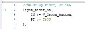
Figure 3. Calling the timer function, which is a TON as we established in the VAR header.
With this function, our on-delay timer will operate as expected. Next, we simply need to connect the output to some sort of indicator that will show us the success of the project.
In the following line, we enable an indicator light when the timer is finished.
V_Green_light := light_timer_on.Q;
Load this new program and log in to the controller.
You can now view the live status of all the variables by expanding the TON from the VAR list.

Figure 4. The live status of all data variables can be viewed when logged on to the PLC.
Off-Delay Timer (TOF) in TwinCAT
We won’t have much new information to introduce for TOF implementation since the process is nearly the same as for the TON. In the variable list, we first create a new listing called light_timer_off : TOF; which must be named differently from any other variables within this local POU called MAIN.
The function is called in exactly the same manner as the TON, and we can program them both simultaneously. I have used the yellow button and light as the input and output, respectively, for my TOF.
light_timer_off(
IN := V_Yellow_button,
PT := #3s
);
V_Yellow_light := light_timer_off.Q;
The behavior of a TOF is a bit more confusing than the TON. This is thoroughly explained in any PLC timer tutorial, but as a quick recap, the off-delay function keeps an output running for a short duration after the end of an event. In our program, the Q bit operating the yellow light will energize the instant the yellow button is pressed. After releasing the button, the light will remain energized for 3 seconds, then turn off.
The behavior of the tags, as always, can be seen by expanding the TOF variable.
Footnote on Timer Variables
For some PLC languages, the timer variables (tags) have different names, and it’s important to understand the relationship:
| IEC Notation | Other Notation |
| IN | EN |
| PT | PRE |
| ET | ACC |
| Q | DN |
TT (timer timing) is another tag with no formal IEC definition, but it can be replicated with simple logic: “timer input is energized but timer done is not energized” for an on-delay timer, and “timer input is no longer energized but timer done is still active” for an off-delay timer.
Counters in TwinCAT
As we march forward with understanding TwinCAT functions, the syntax continues to be consistent. First, we must define the new CTU in our variable list. I have called mine ‘part_counter.’
The variables used in the counter are slightly different: the bool called CU is the rising-edge trigger input, the bool RESET is a trigger which sets the current count value back to zero, and the integer PV is the preset target value that will energize the counter’s Q bit.

Figure 5. The variables contained inside a counter data type.
With this knowledge, we can fashion the function call similarly to the timers, but with these three new inputs:
part_counter(
CU := V_Red_button,
RESET := V_Third_button,
PV := 5
);
V_Red_light := part_counter.Q;

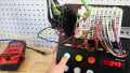
Figure 6. Illuminate buttons for testing timers and counters; the second (non-colored) row of buttons uses the labels of ‘first’, ‘second’, and ‘third’.
With this code downloaded, we can press the red button 5 times, and the red light will energize. Pressing the third button (which, on this starter kit, is the third white button in the lower row) will reset the counter back to zero.

Figure 7. The entire code (variables and functions) for testing our TON, TOF, and CTU.
What about Logical Operators?
These examples have contained very simple inputs and outputs. One variable triggers the timer/counter, which, in turn, triggers a single indicator when complete. In the next article, we’ll dive into a major building block of industrial programming: logical operators like AND, OR, and NOT; how can we use these to build more complex structures that compare many variables for sequential logic?
Related Content


hımmm, thanks
will be fine if you embedded the article by GIF or even small tutorial video