 Facebook
 Google
 GitHub
 Linkedin
Pneumatic Actuator Response
A limitation inherent to pneumatic valve actuators is the amount of air flow required to or from the actuator to cause rapid valve motion. This is an especially acute problem in all-pneumatic control systems, where the distance separating a control valve from the controller may be substantial:

The combined effect of air-flow friction in the tube, flow limitations inherent to the controller mechanism, and volume inside the valve actuator conspire to create a sluggish valve response to sudden changes in controller output signal, not unlike the response of an RC (resistor-capacitor) time-delay circuit where a step-change in voltage input results in an inverse exponential output signal.
If the pneumatic valve actuator is driven by an I/P transducer instead of directly by a pneumatic controller, the problem is lessened by the ability to locate the I/P close to the actuator, thus greatly minimizing tube friction and thus minimizing the “time constant” (\(\tau\)) of the control valve’s response:
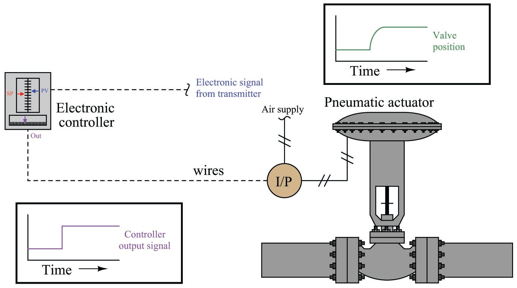
Still, if the pneumatic actuator is particularly large in volume, an I/P transducer may experience trouble supplying the necessary air flow rate to rapidly actuate the control valve. Certainly the problem of time delay is reduced, but not eliminated, by the close-coupled location of the I/P transducer to the actuator.
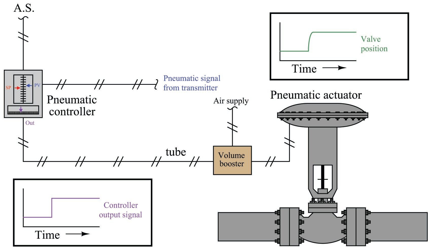
One way to improve valve response in either type of system (full-pneumatic or I/P-driven) is to use a device known as a volume booster to source and vent compressed air for the valve actuator. A “volume booster” is a pneumatic device designed to reproduce a pneumatic pressure signal (1:1 ratio), but with far greater output flow capacity. In electrical terms, a volume booster is analogous to a voltage follower: a circuit designed to boost current to a load, without boosting or diminishing voltage. A 3 to 15 PSI pneumatic pressure signal applied to the input of a volume booster will result in an identical output signal (3 to 15 PSI), but with greatly enhanced flow capacity.
A pneumatic control system equipped with a volume booster would look something like this:
Of course, enhanced air flow to and from the actuator does not completely eliminate time delays in valve response. So long as the flow rate into or out of an actuator is finite, some time will be required to change pressure inside the actuator and thus change valve position. However, if the actuator volume cannot be reduced for practical reasons of actuating force (larger diaphragm or piston area needed for more force, also resulting in more volume for any given stroke length), then the only variable capable of reducing time lag is increased air flow rate, and a volume booster directly addresses that deficiency.
Internally, a volume booster’s construction is not unlike a manually-adjusted pressure regulator:

In either mechanism, an internal diaphragm senses output pressure and acts against a restraining force (either a spring preloaded by a hand adjustment screw or an external pressure signal acting on another diaphragm) to position an air flow throttling/venting mechanism. If the output pressure is less than desired, the diaphragm moves down to open the air sourcing plug and supply additional air volume to the output. If the output pressure is greater than desired, the diaphragm moves up to shut off the sourcing plug and open up the venting port to relieve air pressure to atmosphere.
Interested in more information about fluid control and valves?
Check out our fluid calculators:
Related Textbook Pages:
Related Technical Articles:
- Info Byte: Definition of Pressure and Flow in Fluid Systems
- Barg vs Bara: Understanding Absolute and Gauge Pressure
- Common Control Valve Issues and Troubleshooting
