 Facebook
 Google
 GitHub
 Linkedin
Control Valve Actuators
The purpose of a control valve actuator is to provide the motive force to operate a valve mechanism. Both sliding-stem and rotary control valves enjoy the same selection of actuators: pneumatic, hydraulic, electric motor, and hand (manual).
Pneumatic actuators
Pneumatic actuators use air pressure pushing against either a flexible diaphragm or a piston to move a valve mechanism. The following photograph shows a cut-away control valve, with a pneumatic diaphragm actuator mounted above the valve body. You can see the large coil spring providing default positioning of the valve (air pressure acting against the diaphragm moves the valve against the spring) and the rubber diaphragm at the very top. Air pressure applied to the bottom side of the diaphragm lifts the sliding stem of the valve in the upward direction, against the spring’s force which tries to push the stem down:

The amount of force (\(F\)) in units of pounds generated by any fluid pressing against any surface is equal to the fluid’s pressure (\(P\)) in units of PSI multiplied by the surface area (\(A\)) in units of square inches (\(F = PA\)). In the case of a circular diaphragm, with area equal to \(\pi r^2\), the complete formula for force is \(F = P \pi r^2\). For example, a control valve diaphragm 14 inches in diameter (radius = 7 inches) with an applied air pressure of 15 PSI generates a linear force of 2309 pounds.
Air pressure required to motivate a pneumatic actuator may come directly from the output of a pneumatic process controller, or from a signal transducer (or converter) translating an electrical signal into an air pressure signal. Such transducers are commonly known as I/P or “I to P” converters, since they typically translate an electric current signal (I) of 4 to 20 mA DC into an air pressure signal (P) of 3 to 15 PSI.
The following photographs show I/P transducers of different make and model. A Fisher model 846 appears in the upper-left photograph, while an older Fisher model 546 appears in the upper-right (with cover removed). A Foxboro model E69F I/P appears in the lower-left photograph, while a Moore Industries model IPT appears in the lower-right:


Despite their differing designs and appearances, they all function the same: accepting an analog DC current signal input and a clean supply air pressure of about 20 PSI, outputting a variable air pressure signal proportional to the electric current input. An interesting feature to compare between these four I/P transducers is their relative ruggedness. Every transducer shown except the Moore Industries model (lower-right) is built to withstand direct exposure to a process atmosphere, hence the heavy cast-metal housings and electrical conduit fittings. The Moore Industries unit is intended for a sheltered location, and may be plugged in to a “manifold” with several other I/P transducers to form a compact bank of transducers capable of driving air pressure signals to several valve actuators.
Some pneumatic valve actuators are equipped with handwheels which are used to manually position the valve in the event of air pressure failure. The next photograph shows a sliding-stem control valve with pneumatic diaphragm actuator and a “handwheel” on the top:

Note the three manual valves located around the control valve: two to block flow through the control valve and one to bypass flow around the control valve in the event of control valve failure or maintenance. These manual valves happen to be of the gate design, with rising-stem actuators to clearly show their status (stem protruding = open valve ; stem hidden = closed valve). Such block-and-bypass manual valve arrangements are quite common in the process industries where control valves fulfill critical roles and some form of manual control is needed as an emergency alternative.
Note also the air pressure tubing between the valve actuator and the air supply pipe, bent into a loop. This is called a vibration loop, and it exists to minimize strain on the metal tubing from vibration that may occur.
Pneumatic actuators may take the form of pistons rather than diaphragms. Illustrations of each type are shown here for comparison:
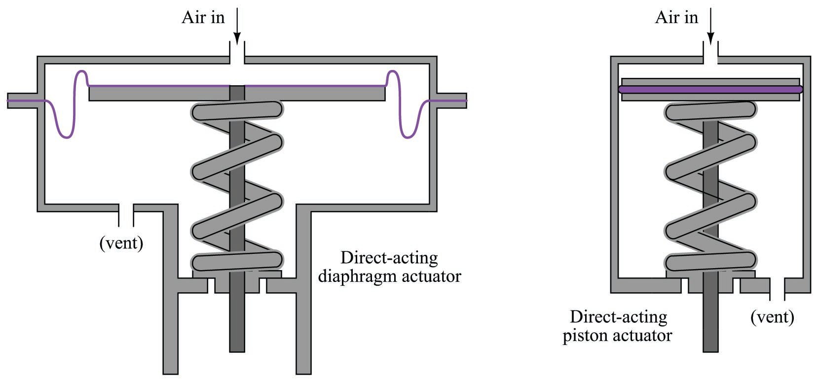
Piston actuators generally have longer stroke lengths than diaphragm actuators, and are able to operate on much greater air pressures. Since actuator force is a function of fluid pressure and actuator area (\(F = PA\)), this means piston actuators are able to generate more force than diaphragm actuators of the same diameter. A 14 inch diaphragm operating at a maximum pressure of 35 PSI generates 5388 pounds of force, but the same size piston operating at a maximum pressure of 150 PSI generates 23091 pounds of force. The combination of greater force and greater displacement yields more work potential for piston actuators than diaphragm actuators of equivalent size, since mechanical work is the product of force and displacement (\(W = Fx\)).
Diaphragm actuators enjoy the definite advantage of less friction than piston actuators. Less friction means greater precision in positioning the valve stem, which gives diaphragm actuators an advantage over piston actuators where precise valve positioning is important, all other factors being equal.
The following photograph of an ultra-high pressure oxygen valve shows a large pneumatic piston actuating a relatively tiny valve body:

Since the only rationale for selecting such a large piston actuator is to generate large actuating force, we may conclude that this relatively small valve body requires an unusually high force to actuate. This is indeed the case, as the process fluid pressure drop across the valve trim in this application happens to be several thousand PSI. This great of a pressure differential, dropped across even a small valve plug, generates substantial force. The actuator must generate even more force than this in order to successfully move the valve, and must do so while limited to the typical instrument air pressure value of 100 PSI. Thus, the only way for the actuator to generate a superior force to the valve plug while working with much less fluid pressure is for the actuator piston to have a much greater area than the plug.
A double-piston pneumatic actuator appears in the next photograph, providing the mechanical force needed to turn an on/off butterfly valve:

In this particular actuator design, a pair of pneumatically-actuated pistons move a rack-and-pinion mechanism to convert linear piston motion into rotary shaft motion to move the butterfly trim. Note the rotary indicator (yellow in color) at the end of the rotary valve stem, showing what position the butterfly valve is in. Note also the travel switch box (black in color) housing multiple limit switches providing remote indication of valve position to the control room.
A rack-and-pinion mechanism looks like this, as viewed looking into the axis of the rotary shaft:

Compressed air applied to the bottom tube (with the top tube vented) pushes both pistons toward the center, spinning the pinion gear counter-clockwise. Applying compressed air to the top tube (with the bottom tube vented) pushes both pistons outward, rotating the pinion gear clockwise.
An example of this actuator design, cut away to reveal its inner workings, appears here:


Another pneumatic piston actuator design uses a simple crank lever instead of a rack-and-pinion gear set to convert the linear piston motion into rotary motion. This next photograph shows such a piston actuator connected to a ball valve:

Perhaps the greatest disadvantage of piston actuators as applied to control valves is friction between the piston’s pressure-sealing ring and the cylinder wall. This is not a problem for on/off control valves, but it may be a significant problem for throttling valves where precise positioning is desired. Diaphragm actuators do not exhibit the same degree of friction as piston actuators because the elastic diaphragm rolls and flexes rather than rubs against a stationary surface as is the case with piston sealing rings.
Hydraulic actuators
Hydraulic actuators use liquid pressure rather than gas pressure to move the valve mechanism. Nearly all hydraulic actuator designs use a piston rather than a diaphragm to convert fluid pressure into mechanical force. The high-pressure rating of piston actuators lends itself well to typical hydraulic system pressures, and the lubricating nature of hydraulic oil helps to overcome the characteristic friction of piston-type actuators. Given the high-pressure ratings of most hydraulic pistons, it is possible to generate tremendous actuating forces with a hydraulic actuator, even if the piston area is modest. For example, hydraulic pressure of 2000 PSI applied to one side of a 3-inch diameter piston will generate a linear thrust exceeding 14000 pounds (7 tons)!
In addition to the ability of hydraulic actuators to easily generate extremely large forces, they also exhibit very stable positioning owing to the non-compressibility of hydraulic oil. Unlike pneumatic actuators, where the actuating fluid (air) is “elastic,” the oil inside a hydraulic actuator cylinder does not yield appreciably under stress. If the passage of oil to and from a hydraulic cylinder is blocked by small valves, the actuator will become firmly “locked” into place. This is an important feature for certain valve-positioning applications where the actuator must firmly hold the valve position in one position.
Some hydraulic actuators contain their own electrically-controlled pumps to provide the fluid power, so the valve is actually controlled by an electric signal. Other hydraulic actuators rely on a separate fluid power system (pump, reservoir, cooler, hand or solenoid valves, etc.) to provide hydraulic pressure on which to operate. Hydraulic pressure supply systems, however, tend to be more limited in physical span than pneumatic distribution systems due to the need for thick-walled tubing (to contain the high oil pressure), the need to purge the system of all gas bubbles, and the problem of maintaining a leak-free distribution network. It is usually not practical to build a hydraulic oil supply and distribution system large enough to cover the entirety of an industrial facility. Another disadvantage of hydraulic systems compared to pneumatic is the lack of intrinsic power storage. Compressed air systems, by virtue of air’s compressibility (elasticity), naturally store energy in any pressurized volumes, and so provide a certain degree of “reserve” power in the event that the main compressor shut down. Hydraulic systems do not naturally exhibit this desirable trait.
A hydraulic piston actuator attached to a large shut-off valve (used for on/off control rather than throttling) appears in the next photograph. Two hydraulic cylinders may be seen above the round valve body, mounted horizontally. Like the pneumatic piston valve shown earlier, this valve actuator uses a rack-and-pinion mechanism to convert the hydraulic pistons’ linear motion into rotary motion to turn the valve trim:

A feature not evident in this photograph is a hydraulic hand pump that may be used to manually actuate the valve in the event of hydraulic system failure.
Self-operated valves
Although not a type of actuator itself, a form of actuation worthy of mention is where the process fluid pressure itself actuates a valve mechanism. This self-operating principle may be used in throttling applications or on/off applications, in gas or liquid services alike. The process fluid may be directly tubed to the actuating element (diaphragm or piston) or passed through a small mechanism called a pilot to modulate that pressure before reaching the valve actuator. This latter design allows the main valve’s motion to be controlled by an adjustable device (the pilot).
A very common application for pilot-operated control valves is gas pressure regulation, especially for fuel gas such as propane or natural gas used to fuel large industrial burners. This next photograph shows a Fisher gas pressure regulator used for regulating the pressure of natural gas fueling an industrial burner:

The following diagram shows how a self-operated, spring-loaded gas pressure regulating valve functions:

Spring tries to force the plug off the seat, while “feedback” gas pressure from the downstream side of the valve acts against a flexible diaphragm to move the plug toward the seat. The less downstream pressure, the more the trim opens up; the more downstream pressure, the more the trim shuts off. This spring establishes the pressure-regulating “setpoint” value for the regulator. If a different setpoint is desired, the spring must be replaced with one having different stiffness.
A variation on this theme is the pilot-loaded or externally-loaded pressure regulator, using a source of external gas pressure to establish the pressure regulation setpoint. Here, a simple manual-adjustment pressure regulator serves as the “pilot” device to send a loading pressure to the top of the main regulator’s actuating diaphragm:

Instead of a stiff internal spring establishing the regulator’s pressure setpoint, the externally-supplied loading pressure does that. Since this loading pressure is easily adjusted by turning the knob on the manual-set pressure regulator, the main regulator now becomes adjustable as well. The pilot mechanism controls the main gas throttling mechanism, hence the name pilot.
This next pilot-operated valve is used in a liquid (wastewater) service rather than gas:

A consumer-grade application for pilot-operated valves is irrigation system control, where the solenoid valves used to switch water flow on and off to sprinkler heads use pilot mechanisms rather than operate the valve mechanism directly with magnetic force. A small solenoid valve opens and closes to send water pressure to an actuating diaphragm, which then operates the larger valve mechanism to start and stop the flow of water to the sprinkler. The use of a pilot allows a relatively small amount of electrical power to control the valve, compared to the amount of electrical power that would be necessary if the solenoid coil were built large enough to actuate the main water valve directly.
A special case of the self-operated valve is the Pressure Relief Valve (PRV) or Pressure Safety Valve (PSV). These valves are normally shut, opening only when sufficient fluid pressure develops across them to relieve that process fluid pressure and thereby protect the pipes and vessels upstream. Like the other self-operated valves, these safety valves may directly actuate using process fluid pressure or they may be triggered by a pilot mechanism sending process fluid pressure to the actuator only above certain pressures. Relief valves using pilots have the advantage of being widely adjustable, whereas non-pilot safety valves usually have limited adjustment ranges.
For more information on overpressure protection devices (including PRVs and PSVs) refer to section 32.5 beginning on the page.
Electric actuators
Electric motors have long been used to actuate large valves, especially valves operated as on/off (“shutoff”) devices. Advances in motor design and motor control circuitry have brought motor-operated valve (MOV) technology to the point where it now competes with legacy actuator technologies such as pneumatic in actuating throttling valves as well.
Most electric valve actuators use a worm gear set to reduce the high rotational speed of the electric motor to a slow rotation suitable for moving a large valve mechanism. An illustration of a worm gear set appears here:

The worm screw looks much like a threaded fastener, with its “threads” properly pitched to engage with the teeth of the worm wheel gear. As the worm screw turns, it slowly pushes or pulls the circumference of the worm wheel, resulting in a large gear ratio (i.e. many turns of the screw are required to produce a single turn of the wheel). This slow-turning wheel may then be used to move a sliding-stem valve by means of a threaded shaft (another screw) or used to directly turn a rotary valve (e.g. butterfly, ball, plug).
An electric actuator appears in the next photograph, providing on/off rotary actuation to a ball valve. This particular electric actuator comes with a hand crank for manual operation, in the event that the electric motor (or the power provided to it) fails:
A small lever to the left of the hand crank actuates a clutch mechanism to engage or disengage the valve mechanism from the electric motor and the hand wheel. This clutch “selects” either the motor or the hand wheel as the prime mover for the valve, to avoid having the hand wheel spin as the motor turns. Unless this lever is first moved to the “manual” position, turning the hand wheel accomplishes nothing.
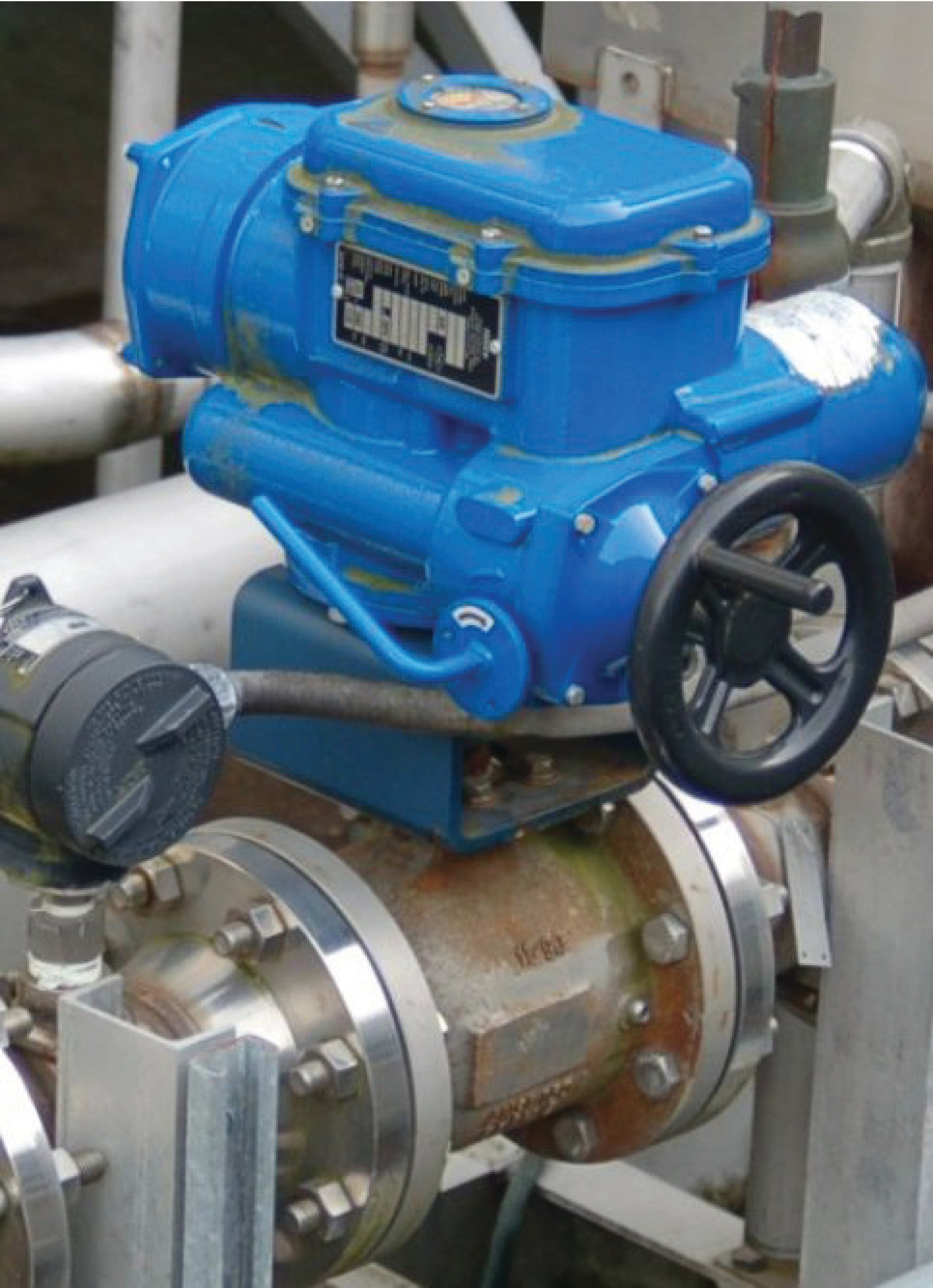
The next photograph shows an electric valve actuator coupled to a large butterfly valve. Although nothing visible in this photograph betrays the nature of this actuator’s signaling, it happens to be digital rather than analog, receiving position commands through a Profibus digital network rather than an analog 4-20 mA current signal:

The shape of the actuator’s metal casing reveals the final gear drive of this actuator as a worm gear set. Note the round shape of the casing where the open/close indicator is located (at the centerline of the butterfly valve stem): this contains the worm wheel. Note immediately to the left of that round casing is a vertically-oriented cylinder shape: this contains the worm screw, which engages with the teeth of the worm wheel. Above the worm screw is a parallel-shaft spur gear set which acts to further reduce the speed of the actuator’s electric motor: the motor shaft terminates in a small gear, which meshes with a larger gear that turns the worm screw shaft. Above the parallel-shaft gear set is the main casing of the actuator, which actually contains its own internal worm gear set. This multiple-stage gear reduction means that the motor spins very fast in comparison to the butterfly element inside the valve and that the butterfly is capable of exerting a fantastic amount of torque in comparison to the torque rating of the electric motor.
Electric motors require no external fluid power system to function, unlike pneumatic or hydraulic actuators. All they require is a source of electrical power (often 480 volts AC, three-phase). Some electric valve actuators even have the capability of operating from the power of an electric battery pack, for reliable operation in the event of a power system outage.
Virtually all electric valve actuators require some form of feedback to indicate the valve’s position. At a minimum, this consists of limit switches to indicate when the valve is fully shut and fully open. For throttling services, an electric actuator requires an actual valve position sensor so that it may precisely adjust the valve to any desired state. This sensor may take the form of a potentiometer, or a variable differential transformer (LVDT or RVDT), or pulse encoder.
This Rotork brand MOV has a digital display at one end showing its closed status both in the text (“Closed Limit”) and symbolically (by the vertical line, which is supposed to represent a closed butterfly element):

In addition to visual indicators of status, electric valve actuators commonly provide auxiliary electrical contacts signaling fully-open and fully-closed positions, which may be used to energize remote indicator lights or discrete input channels of control systems (e.g. PLC). Throttling-service MOVs also provide analog (and/or digital) signaling of valve stem position for remote indication or feedback to an electronic control system.
Hand (manual) actuators
Valves may also be actuated by hand power alone. The following valves are all “manual” valves, requiring the intervention of a human operator to actuate:


Note the threaded stem of the lower-left valve. This stem rises and falls with the handle’s turning, providing a visual indication of the valve’s status. Such an actuator is called a rising-stem design. Also note the chain on the upper-right actuator wheel, allowing operation of the high-mounted valve from a ground-level position.
A hybrid of hand and pneumatic valve actuation is seen on this Valtek brand control valve, where the control valve assembly is actuated by a pneumatic piston actuator but is also equipped with a manually-operated “handwheel”:

A handwheel mechanism may be used to override the pneumatic actuator simply by overpowering it in either direction (i.e. providing a greater force on the valve stem than the piston actuator provides) or it may be left in a neutral position to allow the pneumatic actuator full control over valve stem position. Handwheels may be used to override the control valve’s pneumatic actuator to either the full-open or full-closed positions, or it may simply be used to assert a high- or low-limit “stop” to the valve stem to prohibit stem motion beyond a certain position.
Note the “lockout” tab flipped to the horizontal position near the handwheel, located between two of the handwheel’s spokes. This simple mechanism permits the handwheel to be locked out to prevent accidental turning.
Interested in more information about fluid control and valves?
Check out our fluid calculators:
Related Textbook Pages:
Related Technical Articles:
- Info Byte: Definition of Pressure and Flow in Fluid Systems
- Barg vs Bara: Understanding Absolute and Gauge Pressure
- Common Control Valve Issues and Troubleshooting
