 Facebook
 Google
 GitHub
 Linkedin
Valve Positioners

Why does a valve need a positioner?
Forces such as friction from packing, seals, and differential pressure all conspire to re-position the valve stem so stem travel does not precisely correlate to actuating fluid pressure. Positioners provide a closed-loop system for valve reliability.
The reason why a pneumatic control valve’s stem position corresponds linearly to the amount of air pressure applied to the actuator is because mechanical springs tend to follow Hooke’s Law, where the amount of spring motion (\(x\)) is directly proportional to applied force (\(F = kx\)). A pneumatic actuator applies force as a function of air pressure and piston/diaphragm area (\(F = PA\)), and the spring in turn compresses or stretches to generate an equal and opposite reaction force. The end-result is that actuator pressure linearly translates into valve stem motion (\(x = {PA \over k}\)).
Control Valve Positioner
This linear and repeatable relationship between pneumatic signal pressure and valve stem position holds true if and only if the actuating diaphragm/piston and spring are the sole forces at work on the valve stem. If any other force acts upon this mechanism, the relationship between signal pressure and valve stem position will no longer be ideal.
Unfortunately, there exist many other forces acting on a valve stem besides the actuator force and the spring’s reaction force. Friction from the stem packing is one such force, and reaction force at the valve plug caused by differential pressure across the plug’s area is another. These forces conspire to re-position the valve stem so stem travel does not precisely correlate to actuating fluid pressure.
A common solution to this dilemma is to add a positioner to the control valve assembly. A positioner is a motion-control device designed to actively compare stem position against the control signal, adjusting pressure to the actuator diaphragm or piston until the correct stem position is reached:

Positioners essentially act as control systems within themselves: the valve’s stem position is the process variable (PV), the command signal to the positioner is the setpoint (SP), and the positioner’s signal to the valve actuator is the manipulated variable (MV) or output. Thus, when a process controller sends a command signal to a valve equipped with a positioner, the positioner receives that command signal and applies as much or as little air pressure to the actuator as needed in order to achieve that desired stem position. Thus, the positioner will “fight” against any other forces acting on the valve stem to achieve crisp and accurate stem positioning according to the command signal. A properly functioning positioner ensures the control valve will be “well-behaved” and obedient to the command signal.
Examples of Pneumatic Valve Positioners
The following photograph shows a Fisher model 3582 pneumatic positioner mounted to a control valve. The positioner is the grey-colored box with three pressure gauges on its right-hand side:
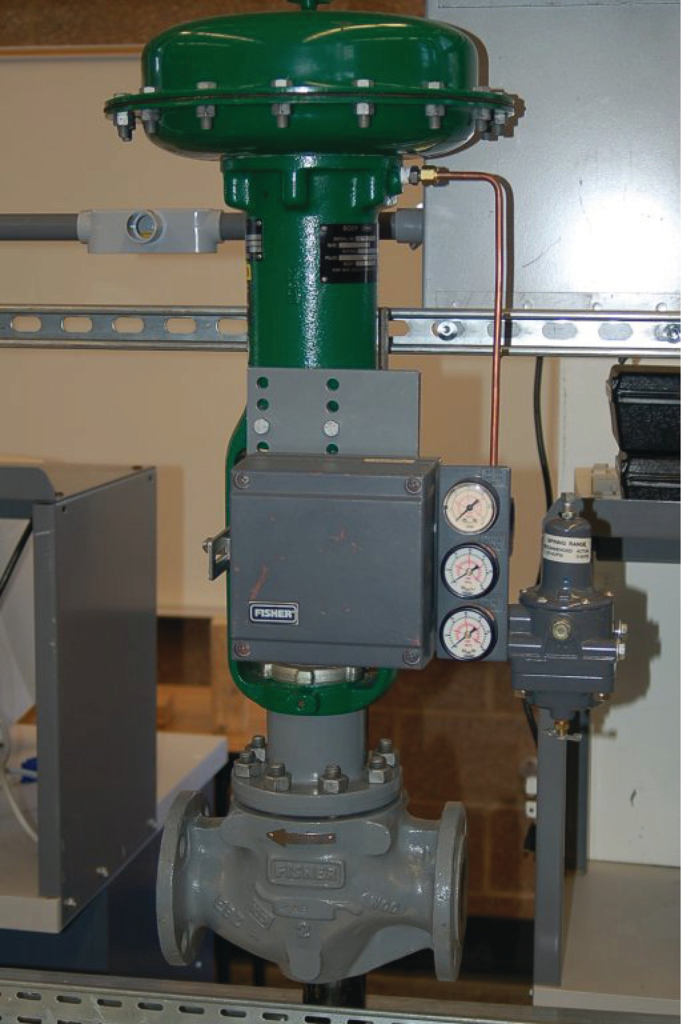
On the left-hand side of this positioner may be seen part of the feedback mechanism: a metal bracket bolted to the valve stem connector, linking to an arm coming out of the positioner’s side. Every control valve positioner must be equipped with some means to sense the position of the valve’s stem, otherwise the positioner could not compare the valve stem’s position against the command signal.
A more modern positioner appears in the next photograph, the Fisher DVC6000 (again, the grey-colored box with pressure gauges on its right-hand side):

Like the older model 3582 positioner, this DVC6000 model uses a feedback linkage on the left-hand side to sense the valve stem’s position. The even newer model DVC6200 uses a magnetic Hall Effect sensor to sense the position of a magnet bolted to the valve stem. This non-mechanical position feedback design eliminates backlash, wear, interference, and other potential problems associated with mechanical links. Better feedback is essential to better valve positioning.
Control valve positioners are typically constructed in such a way to source and vent high air flow rates, such that the positioner also fulfills the functionality of a volume booster850. Thus, a positioner not only ensures more precise valve stem positioning, but also faster stem velocity (and shorter time delays) than if the valve actuator were directly “powered” by an I/P transducer.
Valve Seating
Another advantage of adding a positioner to a pneumatically actuated control valve is superior valve seating (tight shutoff). This benefit is not obvious at first inspection, and so some explanation is in order.
First, one must understand that mere contact between the plug and seat within a sliding-stem valve is not enough to ensure tight shut-off. Rather, the plug must be forcefully pressed down onto the seat in order to fully shut off all flow through the valve. Anyone who has ever tightened the handle on a leaking hose bib (garden spigot) intuitively understands this principle: a certain amount of contact force between the plug and the seat is necessary in order to slightly deform and thereby mold those two components to a perfect fluid-tight fit. The technical term for this mechanical requirement is seat load.
Imagine if you will a diaphragm-actuated, sliding-stem, air-to-open control valve with a bench set range of 3 to 15 PSI. At an applied actuator pressure of 3 PSI, the diaphragm generates just enough force to exactly overcome the actuator spring’s pre-load force, but not enough force to actually move the plug off the seat. In other words, at 3 PSI diaphragm pressure, the plug is touching the seat but with little or no force to provide a tight shut-off seal. If this control valve is directly powered by an I/P transducer with a 3-15 PSI calibrated range, it means the valve will be barely shut at a 0% signal value (3 PSI) rather than tightly shut off. In order to fully force the valve plug against the valve seat to achieve a tight seal, all air pressure would have to be vented from the diaphragm to ensure no diaphragm force opposing the spring. This is impossible with an I/P having a calibrated range of 3-15 PSI.
Now imagine that exact same valve equipped with a positioner, taking the 3-15 PSI signal from the I/P and using it as a command (setpoint) for valve stem position, applying as much or as little pressure to the diaphragm as necessary to achieve the desired stem position. Proper positioner calibration is such that the valve stem does not begin to lift until the signal has risen slightly above 0%, which means at 0% (4 mA) the positioner will be trying to force the valve to a slightly negative stem position. In attempting to achieve this impossible demand, the positioner’s output will saturate low, applying no pressure whatsoever to the actuating diaphragm, resulting in full spring force applied by the plug against the seat. A comparison of the two scenarios is shown here:

While positioners are beneficial on spring-equipped valve actuators, they are absolutely essential for some other styles of actuators. Consider the following double-acting pneumatic piston actuator which has no spring:

Without a spring providing a restraining force to return the valve to a “fail-safe” position, there exists no Hooke’s Law relationship between applied air pressure and stem position. A positioner must alternately apply air pressure to both surfaces of the piston to raise and lower the valve stem.
Electric control valve actuators are another class of actuator design absolutely requiring some form of positioner system, because an electric motor is not “aware” of its own shaft position in order that it may precisely move a control valve. Thus, a positioner circuit using a potentiometer or LVDT/RVDT sensor to detect valve stem position and a set of transistor outputs to drive the motor is necessary to make an electric actuator responsive to an analog control signal.
Force-Balance Pneumatic Positioner
A simple force-balance pneumatic valve positioner design appears in the following cutaway illustration:

The control signal for this valve is a 3 to 15 PSI pneumatic signal, coming from either an I/P transducer or a pneumatic controller (neither one shown in the illustration). This control signal pressure applies an upward force on the force beam, such that the baffle tries to approach the nozzle. Increasing backpressure in the nozzle causes the pneumatic amplifying relay to output a greater air pressure to the valve actuator, which in turn lifts the valve stem up (opening up the valve). As the valve stem lifts up, the spring connecting the force beam to the valve stem becomes further stretched, applying additional force to the right-hand side of the force beam. When this additional force balances the bellows’ force, the system stabilizes at a new equilibrium.
Like all force-balance systems, the force beam motion is constrained by the balancing forces, such that its motion is negligible for all practical purposes. In the end, equilibrium is achieved by one force balancing another, like two teams of people pulling oppositely on a length of rope: so long as the two teams’ forces remain equal in magnitude and opposite in direction, the rope will not deviate from its original position.
The following photograph shows a PMV model 1500 force-balance positioner used to position a rotary valve actuator, with the cover on (left) and removed (right):


The 3-15 PSI pneumatic control signal enters into the bellows, pushing downward on the horizontal force beam (colored black). A pneumatic pilot valve assembly at the left-hand side of the force beam detects any motion, increasing air pressure to the valve actuating diaphragm if any downward motion is detected and releasing air pressure from the actuator if any upward motion is detected:

As compressed air is admitted to the valve actuator by this pilot valve assembly, the rotary valve will begin to rotate in the open direction. The shaft’s rotary motion is converted into a linear motion inside the positioner by means of a cam: a disk with an irregular radius designed to produce linear displacement from angular displacement:

A roller-tipped follower at the end of a gold-colored beam rides along the cam’s circumference. Cam motion is translated into linear force by the compression of a coil spring directly against the force of the pneumatic bellows on the force beam. When the cam moves far enough to compress the spring enough to balance the additional force generated by the bellows, the force beam return to its equilibrium position (very nearly where it began) and the valve will stop moving.
If you closely examine this last photograph, you will see the positioner’s zero screw adjustment: the threaded rod extending below the gold-colored beam. This screw adjustment biases the amount of spring compression, making the positioner mechanism “think” the cam is in a different position. For example, turning this threaded rod clockwise (as viewed from the slotted end where a screwdriver would engage) further compresses the spring, pushing up with greater force on the dark-colored bar, achieving the same effect as if the cam had rotated counter-clockwise slightly. This makes the positioner take action to rotate the cam clockwise to compensate, closer toward the 0% valve stem position.
Even though the cam and follower in this positioner mechanism actually do move with valve stem motion, it is still considered a force-balance mechanism because the beam connected to the pilot valve does not move appreciably. The pilot valve always comes to rest at its equilibrium position through a balancing of forces on the beam.
Motion-Balance Pneumatic Positioner
Motion-balance pneumatic valve positioner designs also exist, whereby the motion of the valve stem counteracts motion (not force) from another element. The following cutaway illustration shows how a simple motion-balance positioner would work:

In this mechanism, an increasing signal pressure causes the beam to advance toward the nozzle, generating increased nozzle backpressure which then causes the pneumatic amplifying relay to send more air pressure to the valve actuator. As the valve stem lifts up, the upward motion imparted to the right-hand end of the beam counters the beam’s previous advance toward the nozzle. When equilibrium is reached, the beam will be in an angled position with the bellows’ motion balanced by valve stem motion.
The following photograph shows a close view of a Fisher model 3582 pneumatic motion-balance positioner’s mechanism:
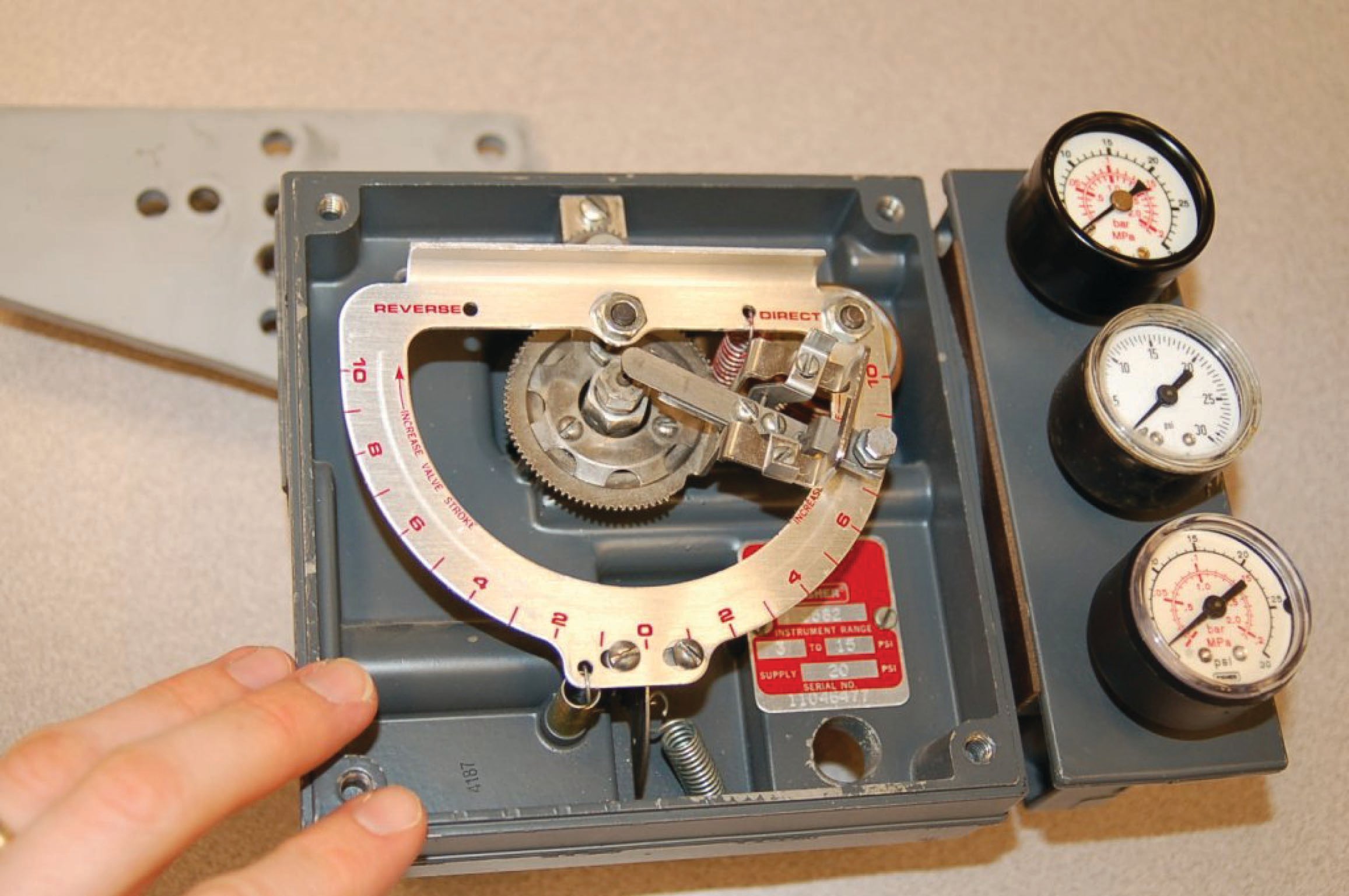
At the heart of this mechanism is a D-shaped metal ring translating bellows motion and valve stem motion into flapper (baffle) motion. As the bellows (located underneath the upper-right corner of the D-ring) expands with increasing pneumatic signal pressure, it rocks the beam along its vertical axis. With the positioner set for direct-acting operation, this rocking motion drives the flapper closer to the nozzle, increasing backpressure and sending more compressed air to the valve actuator:

As the valve stem moves, a feedback lever rotates a cam underneath the bottom-most portion of the D-ring. A roller-tipped “follower” riding on that cam translates the valve stem’s motion to another rocking motion on the beam, this time along the horizontal axis. Depending on how the cam has been fixed to the feedback shaft, this motion may rock the flapper farther away from the nozzle or closer toward the nozzle. This selection of cam orientation must match the action of the actuator: either direct (air to extend the stem) or reverse (air to retract the stem).
The D-ring mechanism is rather ingenious, as it allows convenient adjustment of span by angling the flapper (baffle) assembly at different points along the ring’s circumference. If the flapper assembly is set close to horizontal, it will be maximally sensitive to bellows motion and minimally sensitive to valve stem motion, forcing the valve to move farther to balance small motions of the bellows (long stroke length). Conversely, if the flapper assembly is set close to vertical, it will be maximally sensitive to valve stem motion and minimally sensitive to bellows motion, resulting in little valve stroke (i.e. the bellows needs to expand greatly in order to balance a small amount of stem motion).
Electronic Valve Positioners
Recall that the purpose of a valve positioner is to ensure the mechanical valve’s position matches the command signal at all times. Thus, a valve positioner is actually a closed-loop control system in its own right: applying as much or as little pressure to the actuator in order to achieve the commanded valve stem position at all times. Mechanical valve positioners use levers, cams, and other physical components to achieve this closed-loop control.
Valve Position Sensor
Electronic valve positioners, such as the Fisher model DVC6000, use an electronic sensor to detect valve stem position, a microprocessor to compare that sensed stem position against the control signal by mathematical subtraction (error = position \(-\) signal), then a pneumatic signal converter and relay(s) to send air pressure to the valve actuator. A simplified diagram of a generic electronic valve positioner is shown here:

As you can see from this diagram, there is a lot going on inside an electronic positioner. We have not just one, but two control algorithms working together to maintain proper valve position: one monitoring and controlling pressure applied to the actuator (compensating for changes in air supply pressure that might otherwise affect the valve’s position) and the other monitoring and controlling stem position itself, sending a cascaded control signal to the pressure control components.
The command signal (sent from the process loop controller, PLC, or other control system) tells the positioner where the valve stem should be positioned. The first controller inside the positioner (PI) calculates how much air pressure at the actuator should be needed to achieve the requested stem position. The next controller (PID) drives the I/P (current-to-pressure) converter as much as necessary to achieve that pressure. If anything causes the valve stem to not be at the commanded position, the two controllers inside the positioner work together to force the valve to its proper position.
Not only do electronic valve positioners achieve superior position control when compared to mechanical valve positioners, but their array of sensors and digital communication ability provides a new level of diagnostic data both to maintenance personnel and the supervising control system (if programmed to monitor and act on this data). Examples of diagnostic data provided by electronic positioners include:
- Supply air pressure
- Actuator air pressure
- Ambient temperature
- Position and pressure errors
- Total valve stem travel (like an odometer in an automobile)
Additionally, the microprocessor embedded within an electronic valve positioner is capable of performing self-tests, self-calibrations, and other routine procedures traditionally performed by instrument technicians on mechanical valve positioners. Having access to such measurements as total valve stem travel even allows an electronic positioner to predictively calculate packing wear-out time, automatically flagging a maintenance alarm notifying operators and/or instrument technicians when the valve’s stem packing will need to be replaced!
Valve Position Sensor Failure
A useful capability of some “smart” valve positioners – since they monitor actuator air pressure in addition to stem position – is the ability to maintain a respectable degree of valve control in the event of a stem position sensor failure. If the microprocessor detects a failed (off-scale) position feedback signal, it may be programmed to continue operating the valve based on pressure alone: adjusting the applied air pressure to the valve actuator according to the pressure/position function it has recorded in the past. While not strictly functioning as a positioner any more since it cannot sense valve stem position, it may still fulfill its role as a volume booster (compared to the flow capacity of a typical I/P) and give reasonable control over the valve where any other (non-smart) valve positioner would actually make matters worse in the event of losing its stem position feedback. With any purely mechanical positioner, the control valve will typically “saturate” either fully open or fully closed if the stem position feedback linkage falls off. Not so with the best “smart” positioners!
Actuator Pressure vs Valve Stem Position
Perhaps the most significant diagnostic data provided by an electronic positioner is the comparison of actuator pressure versus stem position, usually expressed in the form of a graph. Actuator pressure is a direct reflection of force applied by the actuator to the valve stem, since the relationship between force and pressure for either a piston or a diaphragm is simply \(F = PA\), where area (\(A\)) is constant. Thus, a comparison of actuator air pressure versus stem position is really an expression of force-versus-position for the valve. This so-called valve signature is incredibly useful in identifying and correcting such problems as excessive packing friction, valve trim interference, and plug/seat fit problems.
A screenshot showing a “valve signature” (taken from an Emerson software product called ValveLink, as part of their AMS suite) appears here, showing the behavior of an air-to-open Fisher E-body globe valve:

Two plots of actuator pressure versus stem position are shown in this graph, one red and one blue. The red graph shows the valve’s response in the opening direction where additional pressure is required to overcome packing friction as the valve moves open (up). The blue graph shows the valve as it closes, less pressure applied to the diaphragm now to allow the spring’s compression to overcome packing friction as the valve moves closed (down) to its resting state. The sharp turns at each end of this graph show where the valve stem reaches its end positions and cannot move farther despite further changes in actuator pressure.
Each plot is roughly linear in accordance with Hooke’s Law describing the behavior of the valve spring, where the force applied to a spring is directly proportional to the displacement (compression) of that spring: \(F = kx\). Any departure from a single linear plot indicates some other force(s) besides spring compression and pneumatic force acting on the valve stem. This is why we see two plots vertically offset from each other: packing friction is another force acting on the valve stem in addition to spring compression and the force exerted by air pressure on the actuator diaphragm. The relatively small magnitude of this offset as well as its consistency indicates that packing friction in this valve is “healthy.” The more packing friction this valve experiences, the more vertically-offset the two plots will be.
The sharp down-turn at the left-hand end of the graph where the valve plug contacts the seat is called the seating profile. Located at the end of the plot where the valve closes off, the seating profile holds much useful information about the physical condition of the plug and seat. As these trim parts wear in a control valve, the shape of the seating profile changes accordingly. Irregular seating profiles may diagnose seat erosion, galling, or a number of other maladies.
By zooming in on the lower-left end of the valve signature graph, the seating profile may be examined in fine detail. A seating profile taken of a Fisher E-body globe valve in pristine condition appears here:

If the maintenance staff of a particular facility are diligent enough to record the valve signatures of its control valves after assembly or rebuild, the “original” signature of any particular control valve may be compared against the signature of the same control valve taken at any later date, allowing qualitative determinations of wear without having to disassemble the valves for inspection.
Interestingly, this relationship of actuator pressure (force) to stem position is also available in the electronic positioners used with some modern electrically-actuated valves. In the case of an electric actuator, force applied to the valve stem directly relates to motor current, which is easily measured and interpreted by the electronic positioner. Thus, even with a different actuator technology, the same kind of diagnostic data may be presented in graphical form for the purpose of more easily diagnosing valve problems. These diagnostics apply even to open/close motor-operated valves not used for throttling service, and are especially useful on gate, plug, and ball-type shut-off valves where seat engagement is substantial for tight shut-off.
Interested in more information about fluid control and valves?
Check out our fluid calculators:
Related Textbook Pages:
Related Technical Articles:
- Info Byte: Definition of Pressure and Flow in Fluid Systems
- Barg vs Bara: Understanding Absolute and Gauge Pressure
- Common Control Valve Issues and Troubleshooting
