 Facebook
 Google
 GitHub
 Linkedin
Split-Range Control
There are many process control applications in the industry where it is desirable to have multiple control valves respond to the output of a common controller. Control valves configured to follow the command of the same controller are said to be split-ranged, or sequenced.
Split-ranged control valves may take different forms of sequencing. A few different modes of control valve sequencing are commonly seen in the industry: complementary, exclusive, and progressive.
Complementary Valve Sequencing
The first type of control valve sequencing is a mode where two valves serve to proportion a mixture of two fluid streams, such as this example where base and pigment liquids are mixed together to form colored paint:

Both base and pigment valves operate from the same 3 to 15 PSI pneumatic signal output by the I/P transducer (AY), but one of the valves is Air-To-Open while the other is Air-To-Close. The following table shows the relationship between the valve opening for each control valve and the controller’s output:
| Controller | I/P output | Pigment valve | Base valve |
|---|---|---|---|
| 0% | 3 PSI | fully shut | fully open |
| 25% | 6 PSI | 25% open | 75% open |
| 50% | 9 PSI | half-open | half-open |
| 75% | 12 PSI | 75% open | 25% open |
| 100% | 15 PSI | fully open | fully shut |
An alternative expression for this split-range valve behavior is a graph showing each valve opening as a colored stripe of varying width (wider representing further open). For this particular mode of split-ranging, the graph would look like this:

With this form of split-ranging, there is never a condition in the controller’s output range where both valves are fully open or fully shut. Rather, each valve complements the other’s position.
An alternative to complementary valve sequencing in a process where two fluid streams mix (or diverge) is to use one three-way valve rather than a pair of two-way valves:

A photograph of a three-way globe valve mixing hot and cold water to control temperature is shown here:
Exclusive Valve Sequencing
Other applications for split-ranged control valves call for a form of valve sequencing where both valves are fully closed at a 50% controller output signal, with one valve opening fully as the controller output drives toward 100% and the other valve opening fully as the controller output goes to 0%. The nature of this valve sequencing is to have an “either-or” throttled path for process fluid. That is, either process fluid flows through one valve or through the other, but never through both at the same time.
A practical example of this form of split-ranging is reagent feed for a pH neutralization process, where the pH value of process liquid is brought closer to neutral by the addition of either acid or caustic reagent liquids:

Here, a pH analyzer monitors the pH value of the liquid solution and a single pH controller commands two reagent valves to open when needed. If the process pH begins to increase, the controller output signal increases as well (direct action) to open up the acid valve. The addition of acid to the mixture will have the effect of lowering the mixture’s pH value. Conversely, if the process pH begins to decrease, the controller output signal will decrease as well, closing the acid valve and then opening the caustic valve. The addition of caustic to the mixture will have the effect of raising the mixture’s pH value.
Both reagent control valves operate from the same 3 to 15 PSI pneumatic signal output by the I/P transducer (AY), but the two valves’ calibrated ranges are not the same. The Air-To-Open acid valve has an operating range of 9 to 15 PSI, while the Air-To-Close caustic valve has an operating range of 9 to 3 PSI. The following table shows the relationship between the valve opening for each control valve and the controller’s output:
| Controller | I/P output | Acid valve | Caustic valve |
|---|---|---|---|
| 0% | 3 PSI | fully shut | fully open |
| 25% | 6 PSI | fully shut | half-open |
| 50% | 9 PSI | fully shut | fully shut |
| 75% | 12 PSI | half-open | fully shut |
| 100% | 15 PSI | fully open | fully shut |
Again, we may express the two valves’ exclusive relationship in the form of a graph, with colored stripes representing valve opening:

Exclusive-sequenced control valves are used in applications where it would be undesirable to have both valves open simultaneously. In the example given of a pH neutralization process, the goal here is for the controller to add either acid reagent or caustic reagent to “push” the pH value either direction as needed. However, simultaneously adding both acid and caustic to the process would be wasteful, as one reagent would simply neutralize the other with no benefit to the process liquid itself.
Progressive Valve Sequencing
The third form of control valve sequencing is used to expand the operating range of flow control for some fluid beyond that which a single control valve could muster. Once again pH control provides a suitable example to illustrate an application of this form of sequencing.
pH is an especially challenging application of process control because the dynamic range of the process is enormous. Each unit of pH value change represents a ten-fold change in hydrogen ion concentration within the process liquid. This means the difference in ion concentration between a process liquid having a value of 10 pH and a process liquid having a value of 7 pH (a pH difference of 3) is a factor of one thousand (\(10^3\))! Consequently, the flow rate of reagent necessary to neutralize a process liquid stream may vary widely. It is quite possible that a control valve sized to throttle minimum flow will simply be too small to meet the demands of high flow when needed. Yet, a control valve sized large enough to meet the maximum flow rate may be too large to precisely “turn down” when just a trickle of reagent is needed.
This same general control problem was encountered by automotive engineers in the days when carburetors were used to mix gasoline with air prior to combustion in an engine. A carburetor is a mechanical air flow control device using a “butterfly” valve element to throttle air flow into the engine, and a venturi element producing vacuum to aspirate fuel droplets into the air stream to create an air-fuel mixture. A carburetor with a butterfly valve and flow tube sized to idle well and respond to the needs of in-town driving would not flow enough air to provide good high-speed performance. Conversely, a large carburetor suitable for driving at racing speeds would offer poor control at low-speed and idling operation. Their solution to this problem was the progressive carburetor, having two butterfly valves to throttle the flow of air into the engine. One butterfly valve passed low amounts of air flow only, while a larger butterfly valve opened up only when the accelerator pedal was nearly at its maximum position. The combination of two differently-sized butterfly valves – progressively opened – gave drivers the best of both worlds. Now, an automobile engine could perform well both at low power levels and at high power levels.
On a fundamental level, the problem faced in pH control as well as by early automotive engineers is the same thing: insufficient rangeability. Some processes demand a greater range of control than any single valve can deliver, and it is within these processes that a pair of progressively-sequenced control valves is a valid solution.
Applying this solution to a pH control process where the incoming liquid always has a high pH value, and must be neutralized with acid:
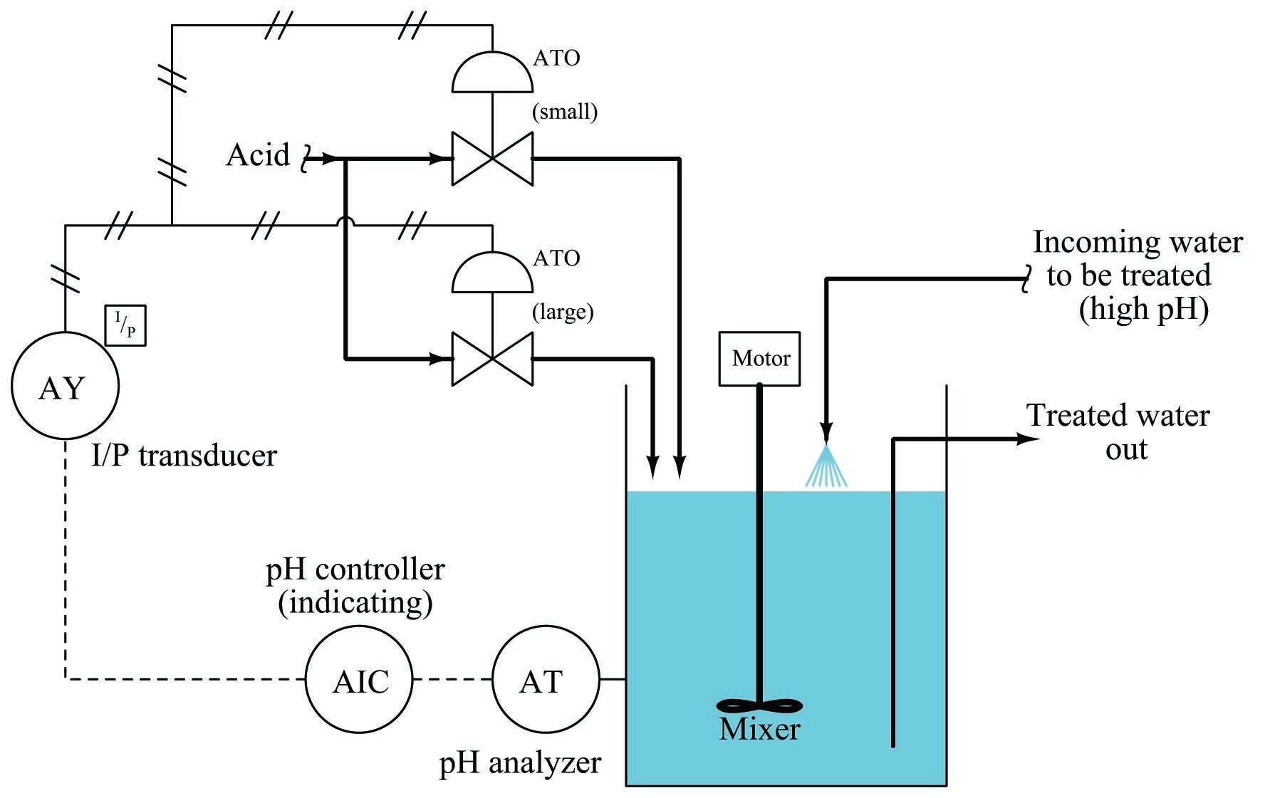
Proper sequencing of the small and large acid control valves is shown in the table and the graph:
output (\%) & (PSI) & (stem position) & (stem position) \cr
| Controller | I/P output | Small acid valve | Large acid valve |
|---|---|---|---|
| 0% | 3 PSI | fully shut | fully shut |
| 25% | 6 PSI | half-open | fully shut |
| 50% | 9 PSI | fully open | fully shut |
| 75% | 12 PSI | fully open | half-open |
| 100% | 15 PSI | fully open | fully open |

With the two acid control valves sequenced progressively, the control system will have significantly more rangeability necessary to regulate pH under widely varying process conditions.
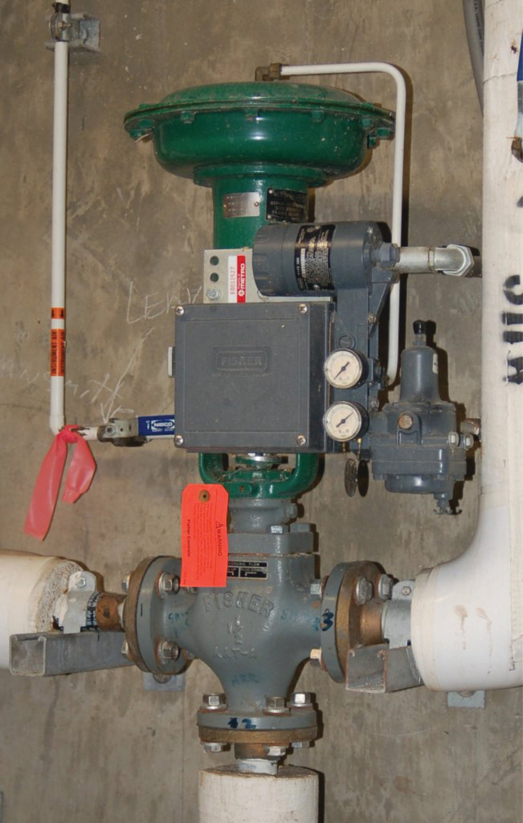
A photograph showing a pair of progressively sequenced control valves used to control boiler feedwater to the high-pressure (“HP”) drum on a large power boiler is shown here:

One small control valve (horizontal, with a green actuator) is the first to open from 4 to 12 mA. A larger control valve (vertical, with a red actuator) is the next to open from 12 mA to 20 mA. Under normal (full-power) operating conditions, the green valve is wide-open while the larger red valve throttles feedwater to the steam drum. When the boiler is operating in standby (low-power) mode, the red valve is shut while the smaller green valve throttles feedwater to the steam drum. The combination of these two control valves provides better steam drum level control over the boiler’s full range of operation than any single control valve could do alone.
Valve Sequencing Implementations
In all previous control valve sequencing examples shown, both control valves received the same pneumatic signal from a common I/P (current-to-pressure) converter. This means each valve received the exact same pressure signal from the transducer for any given controller output value. Sequencing of the two valves (i.e. making each one respond differently to the same air pressure signal), therefore, was a matter of setting each valve to a different bench-set pressure range.
It should be understood, however, that setting up two control valves with different bench-set ranges is not the only way to split-range a pair of valves. Other ways exist as well, each with its own advantages and disadvantages.
The following illustrations depict several alternative methods for control valve sequencing (split-ranging):

The common pneumatic signal approach (one controller, one I/P transducer) is simple but suffers from the disadvantage of slow response, since one I/P transducer must drive two pneumatic actuators. Response time may be improved by adding a pneumatic volume booster between the I/P and the valve actuators, or by adding a positioner to at least one of the valves. Either of these solutions works by the same principle: reducing the air volume demand on the one common I/P transducer.
Wiring two I/P transducers in series so they share a common signal current is another way to split-range two control valves. This approach does not suffer from slow response since each valve has its own dedicated I/P transducer to supply it with actuating air. We now have a choice where we implement the split ranges: we can do it in the I/P transducers (i.e. each I/P transducer having a different calibration) or in the control valves (i.e. each control valve having a different bench-set pressure range). Since it is generally easier to re-range an I/P than it is to rebuild a control valve with a different spring (to give it a different actuating pressure range), this approach has the advantage of convenient configuration.
A disadvantage of the series-wired I/P strategy is the extra burden placed on the controller’s output signal circuitry: one must be careful to ensure the two series-connected I/P converters do not drop too much voltage at full current, or else the controller may have difficulty driving both devices in series. Another (potential) disadvantage of series-connected valve devices in one current loop is the inability to install “smart” instruments communicating with the HART protocol since multiple devices on the same loop will experience address conflicts. HART devices can only work in hybrid analog/digital mode when there is one device per 4-20 mA circuit.
A popular way to implement split-ranging is to use multiple 4-20 mA outputs on the same controller. This is very easy to do if the controller is part of a large system (e.g. a DCS or a PLC) with multiple analog output channels. If multiple outputs are configured on one controller, each valve will have its own dedicated wire pair for control. This tends to result in simpler wiring than series-wired I/P transducers or positioners since each valve loop is a standard 4-20 mA circuit just like any other (non-split-ranged) control valve loop circuit. It may also be the most practical way to implement split-ranging when “smart” valve positioners are used since the dedicated loop circuits allow for normal operation of the HART protocol with no address conflicts.
An advantage of dual controller outputs is the ability to perform the split-range sequencing within the controller itself, which is often easier than re-ranging an I/P or calibrating a valve positioner. This way, the 4-20 mA signals going to each valve will be unique for any given controller output value. If sequenced as such, the I/P transducer calibration and valve bench-set values may be standard rather than customized. Of course, just because the controller is capable of performing the necessary sequencing doesn’t mean the sequencing must be done within the controller. It is possible to program the controller’s dual analog outputs to send the exact same current signal to each valve, configuring each valve (or each positioner, or each I/P transducer) to respond differently to the identical current signals.
A digital adaptation of the dual-output controller sequencing method is seen in FOUNDATION Fieldbus systems, where a special software function block called “SPLT” exists to provide split-ranged sequencing to two valves. The “SPLT” function block takes in a single control signal and outputs two signals, one output signal for each valve in a split-ranged pair. The function block diagram for such a system appears here:

In this Fieldbus system, a single PID control block outputs a signal to the SPLT block, which is programmed to drive two unique positioning signals to the two valves’ AO (analog output) blocks. It should be noted that while each AO block is unique to its own control valve, the SPLT and even PID blocks may be located in any capable device within the Fieldbus network. With FOUNDATION Fieldbus, control system functions are not necessarily relegated to separate devices. It is possible, for example, to have a control valve equipped with a Fieldbus positioner actually perform its own PID control calculations and split-ranged sequencing by locating those function blocks in that one physical device!
Dual controllers are an option only for specialized applications requiring different degrees of responsiveness for each valve, usually for exclusive or progressive split-ranging applications only. Care must be taken to ensure the controllers’ output signals do not wander outside of their intended ranges, or that the controllers do not begin to “fight” each other in trying to control the same process variable.
An important consideration – and one that is easily overlooked – in split-range valve systems are fail-safe mode. As discussed in a previous section of this chapter (on section [failsafe_design]), the basis of the fail-safe control system design is that the control valve(s) must be chosen to fail in the mode that is safest for the process in the event of actuating power loss or control signal loss. The actions of all other instruments in the loop should then be selected to complement the valves’ natural operating mode.
In control systems where valves are split-ranged in either complementary or exclusive fashion, one control valve will be fully closed and the other will be fully open at each extreme end of the signal range (e.g. at 4 mA and at 20 mA). If the sequencing for a set of complementary or exclusive split-ranged control valves happens after the controller (e.g. different actuator actions) the valves must fail in opposite modes upon loss of controller signal. However, if it is deemed safer for the process to have the two valves fail in the same state – for example, to both fail closed in the event of air pressure or signal loss – we may use dual sequenced controller outputs, achieving either complementary or exclusive control action by driving the two valves with two different output signals. In other words, split-ranging two control valves so they normally behave in opposite fashion does not necessarily mean the two valves must fail in opposite states. The secret to achieving proper failure mode and proper split-range sequencing is to carefully locate where the sequencing takes place in the control system.
As an example of a split-ranged system with opposite valve failure modes, consider the following temperature control system supplying either hot water or chilled water to a “jacket” surrounding a chemical reactor vessel. The purpose of this system is to either add or remove heat from the reactor as needed to control the temperature of its contents. Chemical piping in and out of the reactor vessel has been omitted from this P&ID for simplicity, so we can focus just on the reactor’s temperature control system:

Here, the controller has been configured for dual-output operation, where the output value drives two identical 4-20 mA signals to the control valve positioners, which directly input the current signals from the controller without the need for I/P transducers in between. The hot water valve (TV-37a) is fail-closed (FC) while the cold water valve (TV-37b) is fail-open (FO). Half-range positioner calibrations provide the exclusive sequencing necessary to ensure the two valves are never open simultaneously – TV-37b operates on the lower half of the 4-20 mA signal range (4-12 mA), while TV-37a operates on the upper half (12-20 mA).
Consider the effects of the controller (TIC-37) losing power. Both 4-20 mA signals will go dead, driving both valves to their fail-safe modes: hot water valve TV-37a will fully close, while cold water valve TV-37b will fully open. Now consider the effects of air pressure loss to both valves. With no air pressure to operate, the actuators will likewise spring-return to their fail-safe modes: once again hot water valve TV-37a will fully close, while cold water valve TV-37b will fully open. In both failure events, the two control valves assume consistent states, ensuring maximum cooling to the reactor in the event of an output signal or instrument air failure.
However, suppose we desired both of these valves fail in the closed position in the event of an output signal or instrument air failure, rather than have the cooling valve fail open while the heating valve fails closed. Clearly this would require both TV-37a and TV-37b to be fail-closed (FC), which would mean we must find some other way to sequence their operation to achieve split ranging. Examine this reconfiguration of the reactor temperature control system, using identical control valves (signal-to-open, fail-closed) for both hot and cold water supply, and a controller with exclusively-sequenced 4-20 mA output signals:

Consider the effects of the controller (TIC-37) losing power. Both 4-20 mA signals will go dead, driving both valves to their fail-safe modes: fully closed. Now consider the effects of air pressure loss on both valves. With no air pressure to operate, the actuators will spring-return to their fail-safe modes: once again both control valves fully closed. In both failure events, the two control valves consistently close. The failure modes of both valves are still consistent regardless of the nature of the fault, but note how this scheme allows both valves to fail in the same mode if that is what we deem safest for the process.
As with all fail-safe system designs, we begin by choosing the proper fail-safe mode for each control valve as determined by the safety requirements of the process, not by what we would consider the simplest or easiest-to-understand instrument configurations. Only after we have chosen each valve’s failure mode do we choose the other instruments’ configurations. This includes split-range sequencing: where and how we sequence the valves is a decision to be made only after the valves’ fail-safe states are chosen based on process safety.
Interested in more information about fluid control and valves?
Check out our fluid calculators:
Related Textbook Pages:
Related Technical Articles:
- Info Byte: Definition of Pressure and Flow in Fluid Systems
- Barg vs Bara: Understanding Absolute and Gauge Pressure
- Common Control Valve Issues and Troubleshooting
