Facebook
 Google
 GitHub
 Linkedin
An Overview of Leak Detection Systems
Leak detection systems protect personnel, maintain production rates, and keep the environment safe from contaminating materials. Here, learn about types of leaks and key parts of a leak detection system.
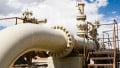
Leak detection systems use different techniques to detect leaks in fluid systems such as piping networks and pressure vessels. In manufacturing industries, fluids are often a basic requirement of the production process, making leak detection systems crucial to proper production.

Figure 1. Leak detection systems monitor piping networks and pressure vessels.
Types of Leakages
Leakages can be classified according to the source. Let’s look at some common types of leaks and how they are monitored.
Valve Leakage
Valves are a basic component of a fluid system that controls the flow of fluid, Their job is to start/stop and increase/decrease the fluid flow. Valves are considered to be leaking when fluid flows even in its closed position.

Figure 2. A leaking valve can affect the start/stop and strength of fluid flow.
Valve leakage causes the fluid to leak into the environment or escape into other parts of the connected system. Possible reasons for valve leakage include damage to the seal and inner seat, improper sizing, and resistance to complete valve closure.
Body Leakage
When fluid flows through the main body container, this is called body leakage. The fluid flows from high pressure to low pressure.
Body leakage is often caused by material defects or damage to the container body, making unfit for operation. The container must be repaired before resuming operations.
Bung Leakage
A bung or stopper is a device fitted on the cylinder neck and affixes the valve to the cylinder. Bungs are frequently loosened and fixed during cylinder refill. The valve controls the flow of gas inside the cylinder. Without a valve, the cylinder cannot be used.

Figure 3. Bungs and stoppers come in a wide array of materials and sizes. Image courtesy of Pipe Equipment Specialists.
Bung leakage occurs when this connection loosens and fluid escapes from the opening between the bung and the cylinder. Bungs can be a common source of leakage, so proper selection of the bung is highly important.
What Causes Leaks in Fluid Systems?
Because fluid systems are generally a larger part of manufacturing and production, there are many causes of leakages in a fluid system. Most causes land in these categories:
- Temperature
- Improper maintenance
- Improper component selection
Let’s look at each of these causes.
Temperature
Significant temperature changes weaken materials and, as a result, the material is not strong enough to also sustain high pressure. This causes the life cycle of the system to shorten.
The material of construction requires strength to withstand temperature changes. If the material is not strong enough, leakages become more common.
Improper Maintenance
Like other equipment and machinery, fluid systems require regular maintenance. If not maintained regularly, the fluid system could eventually malfunction, causing a leak. The consequences of neglected maintenance can be a misalignment of attached components, damaged seals and fittings, and shortened material life.
Improper Selection of Components
Components selected without following the correct design requirements run the risk of leakages.
Factors to consider during material selection include environmental temperature, fluid pressure, and area of application. The physical appearance of components should be error and damage-free.
Leak Detection System Types
There are many leak test mechanisms, each having its own advantages and applications. Selection of tests depends on the type of fluid and level of sensitivity. These parameters direct the selection of a leak detection method. Having the proper detection system in place helps to prevent leaks by taking appropriate preventive measures, making repairs much easier.
Bubble Method
With the bubble method, the part being tested is pressurized with air or gas and submerged in water. Leaks would cause the air or gas to escape, creating bubbles. These bubbles help trace the location of the leak. This method cannot detect pinpoint location but helps to locate the general vicinity.
For other components, soapy water is used instead. The results are the same – soap bubbles are detected near the possible leak.
Pressure Decay Method
In the pressure decay method, the equipment is pressurized up to its design pressure value. The air supply is then stopped and disconnected. Equipment is then monitored for pressure drops. A pressure drop indicates a leakage. The rate of pressure drop with time is measured and calculated. The results point to the current leakage rate of the failed component.
This test is simple to perform and can be used for small leak detection. Note that this test requires calibration every time a different volume or component is used for measurement.
Mass Airflow Method
In the mass airflow method, the component under test is pressurized. Unlike the pressure decay method where air supply is disconnected, air supply remains connected to the component during this test. Air leakage causes the air to enter the component. This is then measured and represents the component’s leakage rate.
The mass airflow method test is insufficient to detect smaller leakages. However, this test does eliminate the need of calibration when using components of different volumes.
What is an Acceptable Level of Leakage?
There are leakages in every component or system – leak-free systems do not exist. When looking at fluid leaks, acceptable levels must be defined. Values greater than the ones agreed upon are not acceptable and cause fluid waste. The systems with values greater than acceptable values are rejected and marked unfit for operation.
Important factors to determine leakage rate are the hole and path length.
Small holes obstruct the flow and result in less leakage. Similarly longer lengths also obstruct the fluid flow and result in less leakage. Leak rate is expressed in SI units of measurements (i.e., mbar-liter/sec). The equation 1 mbar-liter/sec gives the amount of gas necessary to reduce pressure by 1 mbar in a one-liter container in one second.
Advantages of Third-Party Testing
Keeping up with every aspect of maintenance is impossible in huge factories — including leakage testing. Hiring third parties to conduct leakage tests has benefits.

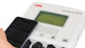
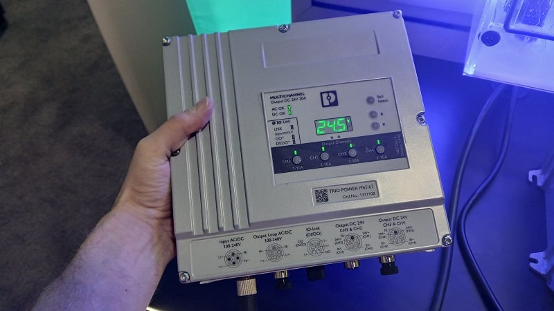
Figure 5. Third-party testing offers the use of an easy-to-follow user interface. Image courtesy of Sciemetric.
There are testing bodies that have expertise in testing mechanisms, standardization, and instrument development. In addition to this, third parties offer the following benefits:
- They are experts in testing procedures. In case of difficulties during the testing process, they are equipped to tackle it with a higher success rate. This enables them to perform leak testing with minimum to no production breakdown.
- They have leak testing instruments for a variety of instruments and ranges. If testing practices are developed in-house, then instruments for every range and size need to be developed and maintained. The expense of this can be saved by outsourcing testing jobs.
- They are experts in fulfilling compliance requirements of regulatory and standardization bodies.
- They have a back-up inventory of required spare parts when replacement is necessary.
Related Content