 Facebook
 Google
 GitHub
 Linkedin
Hands-On with the Arduino Opta Using OpenPLC
Using an Arduino Opta PLC, a few off-the-shelf electrical components, and the popular OpenPLC software environment, automation control concepts can be built on your own test bench.
The Arduino Uno is a well-loved electronics prototyping platform for various maker projects, with the ATmega328 controller at the heart of the user-friendly ecosystem. Besides the traditional Uno, which can be transformed into a low-cost PLC using OpenPLC, the latest addition to the Arduino Pro brand is the Opta.
The Arduino Opta provides extensive support in areas like industrial communication protocols/networking and harsh industrial environmental conditions designs and applications. With features like multiple I/O options, networking, and real-time control, the Opta is an alternative low-cost PLC choice for control and automation engineers.
In this project article, the setup and programming of the Opta using OpenPLC will be presented. The building program instructions for a benchtop DC motor controller will be included in the discussion.

Figure 1. The Arduino Opta. Image used courtesy of Arduino
Setup of OpenPLC
The OpenPLC setup is quite intuitive and only requires downloading an executable installation file from the Autonomy website. OpenPLC can be installed and run on Windows, Linux, and MacOS platforms.
For this project, create a folder with the name Simple_DC_Motor_Control. It is important to create this folder first so that the files generated by OpenPLC will be organized properly. With the folder created, run the OpenPLC program on your development machine. The partial OpenPLC IDE should be visible on the screen, as in Figure 2. The simulation, debug, and programming toolbar will be accessible within the partial OpenPLC IDE.

Figure 2. The partial OpenPLC IDE.
The Program Organization Unit (POU) program name will be Simple_DC_Motor_Control, and we’ll use the LD (Ladder Diagram) language. Click the down arrow button to select LD from the list of five PLC programming languages.
Figure 3 illustrates the completed POU information. Upon completion, in Figure 4, the full IDE will be displayed on the screen.

Figure 3. The completed POU.

Figure 4. The complete OpenPLC IDE.
The next step is to complete the electrical hardware wiring of the project.
Wiring the DC Motor Controls Circuit
This phase of the project consists of two parts: wiring the pushbutton switches (controls) and the DC motor circuit. The conceptual design of the DC motor controller is two pushbutton switches that will be able to operate a small 3 VDC motor. We will use a simple OR logic control function to process the pushbutton switch control signal, turning on the DC motor when either of the two switches is pressed.
The switches will provide a 12 V control signal, which is provided by an external supply, to the Opta’s input terminal block. The internal relay’s dry contact will switch an external 3.3 V power supply to operate the small DC motor. Besides turning on the electromechanical load, an Opta LED status indicator will be visible as well. Figure 5 illustrates the conceptual DC block diagram.

Figure 5. The motor control system block diagram design.
Note: The Opta has a wide operating voltage range of 12 to 24 VDC. A 12 V power supply was used to power the Opta and provide the same voltage for the control signal, but a 24 V power supply can also be used in this project.
The I/O wiring diagram illustrated in Figure 6 shows the electrical connections made between the pushbutton switches, the external power supplies (both 12 V and 3.3 V), and the small DC motor to the Opta PLC. The Opta terminal block is located on top of the micro-PLC. The internal SPST relay contacts terminal connections are located at the bottom of the Opta.

Figure 6. The I/O wiring diagram for the motor controller.
The wiring diagram shown in Figure 7 illustrates the placement of the pushbutton switches, DC motor, and the 3.3 V power supply onto a breadboard. The wiring connections between the pushbutton switches are provided on the diagram. Unlike many PLCs, the inputs are internally bonded to the (-) terminal of the power supply, so we only need to supply power, which in this case comes from the 12 V input.
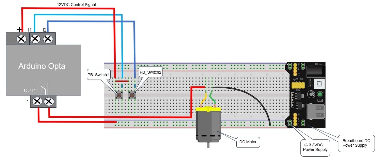
Figure 7. Electrical wiring diagram.
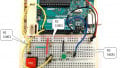
The completed version of the DC motor controller electrical hardware is shown in Figure 8. Now that the electrical wiring phase is completed, the final step is to construct the LD and transfer the program to the Opta.

Figure 8. The assembled DC motor controller.
Ladder Diagram and Program Transfer to the Opta
The final step of the project is to build the motor control LD program using OpenPLC. The LD program with the tag list is shown in Figure 9. The documentation and the physical I/O addresses for the Opta are provided. To build the LD program, follow the instructions from our original Arduino-OpenPLC introduction article.
The LD program file for this project can be downloaded from this github link.

Figure 9. The simple DC motor LD with tag list.
For this transfer, the Opta is tethered to the programming computer via a USB cable. The program is downloaded to the Opta by clicking the “Transfer Program to PLC” button on the OpenPLC IDE toolbar. Upon clicking, a panel will appear, as illustrated in Figure 10. This panel allows for the selection and configuration of the Opta or compatible OpenPLC microcontrollers.
- Selection of board type
- Selection of COM port
- Board type I/O configuration
- Communication

Figure 10. The OpenPLC configuration panel.
From the Board Type selection, choose the Arduino Opta 4.2.1 firmware version of the dropdown list. Select the COM port to which the Opta is attached.
The I/O Config shows the assigned physical addresses to the I/O terminals of the Opta.
The first physical address for the input terminal “I1” (A0) is %IX0.0. The proceeding terminals like “I2” (A1) will be %IX0.1. The remaining input terminal addresses will increase the bit value represented by the number after the decimal point.
The output relay terminal addresses use a similar value scheme except for the base address. Out 1 terminal (relay 1/ status LED1) address is %QX0.0 (D0). The out 2 terminal (relay 2/status LED 2) physical address will be %QX0.1 (D1). Figure 11 shows the I/O physical address scheme for the Opta.

Figure 11. The I/O configuration for the Opta.
Clicking the “Transfer” Icon will return to the main panel window. Attach a USB C cable between the Opta and the OpenPLC development machine. Power the Opta using the external 12 VDC power supply. To transfer the Simple_DC_Motor_Control LD program to the Opta, click “Transfer to PLC” on the panel window. The LD program compilation process will start. The compilation process consists of obtaining various Opta microcontroller resources from various libraries and creating a binary file. The binary file will then be uploaded to the Opta. Initially, the compilation will take several minutes.
After the process is completed, the binary file will be transferred to the Opta. The program transfer will be shown as “Done!” in the compilation window.

Figure 12. The motor control LD program transfer progress output.
To turn on the motor, press either one of the wired solderless breadboard pushbutton switches. Pressing both pushbutton switches will also turn on the DC motor, satisfying the electrical requirement of the OR logic function. The operation of the OR logic function of the assembled motor controller shown in Figure 9 can be viewed here.
Congratulations! You have successfully built a DC motor controller using the Arduino Opta powered by an OpenPLC LD program. The other basic two-input logic or memory functions like the NOT, AND, and SET-RESET can easily be programmed to operate the DC motor by modifying the LD within the OpenPLC IDE.


Great, BTW arduino opta more capable
𝕯𝖗. 𝖂𝖎𝖑𝖈𝖍𝖊𝖗’𝖘 𝖆𝖗𝖙𝖎𝖈𝖑𝖊 𝖔𝖋𝖋𝖊𝖗𝖘 𝖆 𝖈𝖑𝖊𝖆𝖗 𝖆𝖓𝖉 𝖎𝖓𝖋𝖔𝖗𝖒𝖆𝖙𝖎𝖛𝖊 𝖌𝖚𝖎𝖉𝖊 on using the Arduino Opta with OpenPLC for DC motor control. The step-by-step instructions and wiring diagrams make it easy to follow. Definitely a great way to explore the capabilities of the Opta!