Facebook
 Google
 GitHub
 Linkedin
Implementing an OpenPLC Visual Annunciator Flasher Using an Arduino
A flasher can easily be implemented using interlocking timers in a PLC environment on an Arduino Uno using OpenPLC, UiFlow Blockly Code, and a programmable HMI-based LCD unit.
What is a Visual Annunciator?
A visual annunciator provides an alert to indicate important information to users, such as warning or alerting about targeted events, conditions, or alarms in a process. Visual indicators in everyday life typically use LEDs or other light-emitting devices to gain attention through a graphically displayed message. In industrial or manufacturing environments, a stack or light tower is the device used to convey an alarm status. Figure 1 illustrates a typical light stack.

Figure 1. A typical stack light, sometimes called a tower light. Image used courtesy of Patlite
Each color can be activated by means of a PLC initiated by a triggered event, usually initiated manually or automatically using discrete inputs or network communications (IO-Link is common). An individual control wire is provided to operate each stacked light segment. The control wire is connected to the appropriate PLC output terminal. A power supply is required to provide the operating voltage for the signal light’s stacked luminaires, as shown in the typical wiring diagram below.

Figure 2. A typical wiring diagram for a stacked signal light, although wire colors often vary. Image used courtesy of Otennlux
Arduino-OpenPLC Visual Annunciator Concept
The approach that will be used in building our visual annunciator will use a programmable LCD unit capable of displaying various colors for alarm status. The LCD unit has the capability of not only displaying colors, but text messages can be shown as well. The system concept uses four off-the-shelf components:
- The Arduino Uno controller
- One pushbutton switch to simulate the process input signal
- An LED to simulate the stack light
- A programmable LCD unit to simulate a graphical control panel (HMI)
Figure 3 shows the system block diagram of this Arduino-OpenPLC visual annunciator project.

Figure 3. Block diagram of the Arduino-OpenPLC Visual Annunciator. Image used courtesy of the author
The OpenPLC ladder diagram (LD) software will perform an interlocking function of two pulse timers. The pulse timers timed contacts will allow the LED to flash at a predetermined flashing rate.
We will display two alternatives for the graphical HMI: an M5Stack Core or an ESP32 Terminal, both of which are programmable LCD units, providing an alarm indicator based on a specified programmed color. Information on the pulse timers and the M5Stack Core can be found in a previous article. ESP32 Terminal unit information can be found in a separate project with a related code.
Before diving directly into the project build details, here is a quick primer on interlocking timer contacts.
Interlocking Timer Contacts: A Quick Primer
Interlocking timer contacts are useful for creating industrial control application-based flashers. With two timers and their contacts, an interlocking function provides an automated control to switch a logical load on and off, which can easily be tied to a physical output terminal. To illustrate this control-switching function, refer to Figure 4.

Figure 4. A ladder logic program for Interlocking Timers. Image used courtesy of Control Automation Engineering Team
Timer 1 is initiated by a normally closed (N.C.) contact from the Timer 2 output. Initially, Timer 1 output contact is open, thus forcing the Flashing Light to stay off. Timer 1 contact turns on Timer 2 after the [Elapsed Time = Setpoint] time of 500 ms, and the Flashing Light turns on, along with Timer 2.
After a further 500 ms of time has elapsed, Timer 2 output turns on, forcing the first timer off, and then the second timer off, as well as the Flashing Light output off, all in a single ‘reset’ step. On the next scan, the cycle begins again. The Flashing Light on time is delayed by 500 ms.
This ladder logic program is one of many timed switching control operation variants. In our OpenPLC LD, internal memory bits (B1) and (B2) will be used to transition to specified rungs to initiate a pulse timer (TP1) and operate the Green PLT indicator Output Energized (OE) instruction bit.
With an understanding of interlocking timer contacts, let’s build the visual annunciator.
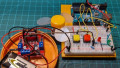
Wiring the Arduino OpenPLC Visual Annunciator
The first step to building the visual annunciator is to wire the PLC unit. The electrical wiring diagram to help build this Arduino-OpenPLC project is shown in Figure 5 below.
The wiring diagram is initially the same as was discussed in the introductory OpenPLC article except for three added resistors.
These news resistors are used to provide the appropriate input voltage for the M5Stack Core and LCD terminal microcontrollers. Both of our HMI terminals are powered by ESP32 microcontrollers for processing I/O control signals, and these pins are only tolerant of voltages up to +3.3 volts. Therefore, to prevent the Arduino from damaging the ESP32 microcontroller’s GPIO pins, the additional resistor circuit provides a 2.5 v control signal to work safely with the processor chip.

Figure 5. The modified Arduino OpenPLC controller electrical wiring diagram. Image used courtesy of the author
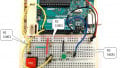
The actual solderless breadboard layout provided in Figure 6 with reference designators may be used in wiring the modified controller.

Figure 6. The solderless breadboard build layout with reference designators. Image used courtesy of the author
The electronic circuit schematic diagram for the Arduino and external hardware connections is shown in Figure 7.

Figure 7. The Arduino electronic circuit schematic diagram. Image used courtesy of the author
Wire extensions are used to attach the M5Stack Core and ESP32 Terminal headers to the Arduino-OpenPLC controller in the breadboard. Figure 8 illustrates adding wire extensions to the jumper harness.

Figure 8. The modified M5Stack jumper harness with wire extensions. Image used courtesy of the author
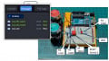
Figures 9 and 10 respectively illustrate the electrical attachment of the M5Stack Core and the ESP32 Terminal to the Arduino-OpenPLC controller. Both connections use a similar header, so the wiring is quite similar between both HMI units.

Figure 9. The M5Stack Core is attached to the Arduino-OpenPLC controller. Image used courtesy of the author
Two small changes are reflected in Figure 10 below when using the ESP32 Terminal unit. This controller uses inverted logic to detect the presence of the signal, supplying 3.3 v from its own GPIO terminal. This requires both a control voltage supply and ground, so a red wire is introduced. Additionally, the 5 v provided directly by the Arduino pin 13 is required to prevent the flow of current from the pin, note the change in placement of the yellow jumper wire below.

Figure 10. The ESP32 Terminal is attached to the Arduino-OpenPLC controller. Image used courtesy of the author
The final step of the visual annunciator project is to add the interlocking timer LD and the HMI-based LCD unit software.
The Visual Annunciator Software
The project has two independent software components:
- One IDE for the M5Stack Core or ESP32 Terminal
- OpenPLC IDE for the interlocking timer LD
The M5Stack Core software was developed using UiFlow Blockly code, a no-code approach to creating visual-appealing UIs for the M5Stack Core. This development software platform aligns well with the OpenPLC, since ladder logic is a no-code structure as well.
The UiFlow Blockly code shown in Figure 11 processes a control signal from the M5 Stack Core produced by the Arduino digital pin 13. A +2.5 v signal generated by the resistor input circuit interface represents a data bit binary 1 value. Conversely, a 0 v signal generated by the resistor input circuit represents a bit value of 0.
When the M5Stack Core receives a binary 1, its display will flash red. A binary 0 value will display green. Green occurs when the pushbutton switch (SW1) is pressed. This triggered event stops the flashing signal from the Arduino digital pin 13. As mentioned before, M5Stack Core setup and programming have been covered previously on Control.com.

Figure 11. The M5Stack Core LCD flasher Blockly code. Image used courtesy of the author
In a similar fashion, the setup and software information for the ESP32 Terminal to flash a green alert can be found in this article (code is found near the end of the linked article).
The OpenPLC interlocking timer tags are shown in Figure 12 and the ladder diagram is provided in Figure 13.
According to the current LD, the flasher will operate only when SW1 is in its default released state. A manual control operation of the interlocking timer (flashing only when SW1 is pressed) can be established by simply changing the Start_Timer bit to an Examine If Closed XIC instruction in Figure 13.
With the software installed on both the controller and the HMI-based LCD display units, a fully functional visual annunciator will be realized. To see the system in operation and verify your own project, check out the videos illustrating the M5Stack Core unit and the ESP32 Terminal unit.

Figure 12. The OpenPLC Interlocking Timer Tags. Image used courtesy of the author

Figure 13. The OpenPLC Interlocking Timer LD. Image used courtesy of the author
Visual Control for Industrial Projects
Congratulations, you have successfully built and tested the visual annunciator Arduino OpenPLC project. You can easily modify the HMI UIs, as well as add additional LED indicators to the solderless breadboard to expand the functionality of this simple demonstration project.
Interested in more Arduino-based PLC content?
- PLC Ladder Logic on an Arduino: Introduction to OpenPLC
- Recreating PLC Ladder Logic in an Arduino C/C++ IDE
- How To: Use the Arduino PLC IDE to Build Basic Ladder Diagrams
- Ladder Logic for the Arduino Opta PLC