Facebook
 Google
 GitHub
 Linkedin
Simplified Prototyping: OpenPLC on an Arduino-Compatible Project Kit
Learn how to rapidly prototype an Arduino-compatible PLC automation circuit without using wires. This hands-on project will illustrate this PLC prototyping concept utilizing the Freenove Projects Kit board.
Check out the Arduino OpenPLC project articles:
PLC Ladder Logic on an Arduino: Introduction to OpenPLC
PLC Ladder Logic on an Arduino: Building a Start-Stop Circuit
The OpenPLC programming environment is a simple, inexpensive way to learn ladder logic programming for industrial control stations. With this software, you can use an Arduino Uno to wire and program simple single-line programs, start/stop circuits, and many more. In this project, you will learn about one tool that can be used to simplify the wiring and allow further hands-on exploration of the OpenPLC software for developing and learning controls automation concepts.
Tools like the one illustrated in this article can accelerate learning and make the process more enjoyable for those who are still learning the basics of wiring and prototyping simple circuits.
Freenove Projects Kit Introduction
In this project, you will explore the Freenove Projects Kit (FPK) board to learn and develop OpenPLC control automation concept applications. The FPK board is an educational training platform to explore electronic control applications using any of the numerous Arduino-compatible boards.
Many Arduino-compatible kits are available, all of them with features and devices that are beneficial to learners. This kit from Freenove is useful and illustrated in this article because of the pre-connected nature of most devices, and those that are not mounted directly to the board can be connected with simple wiring harnesses on headers.
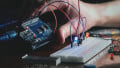
Like the traditional Arduino Uno, this model uses a surface mount device (SMD) microchip ATmega328 microcontroller. Another difference between the FPK control board and a traditional Arduino is the USB connector, which is a version C instead of the traditional USB 2.0 A-male to B-male cable connector. The footprint of the FPK control board has the same physical dimensions as the traditional Arduino Uno. Therefore, the traditional Arduino can easily replace the FPK control board. Figure 1 shows the FPK control board.

Figure 1. The FPK control board (An Arduino Uno Compatible). Image used courtesy of AliExpress
Various through-hole and SMD components like shift register ICs, an LED matrix, a four-digit seven-segment display module, an LED bar, four tactile pushbutton switches, four potentiometers, bus transceiver ICs, Cadmium Sulfide (CdS) photoresistor, thermistor, and brushed motor IC are all mounted directly onto the black printed circuit board (PCB).
Also included with the FPK are additional component accessories like a DC motor, a liquid crystal display (LCD), a keypad, red, green, and blue (RGB) LED, a servo motor, a radio frequency identification (RFID) module, and an infrared receiver. Figure 2 illustrates the FPK with some accessory components.

Figure 2. FPK with electrical-electronic components. Image used courtesy of AliExpress
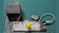
Prototyping an FPK Start/Stop Control Station
With an introduction to FPK and its accessory components, let’s revisit the OpenPLC start/stop control station ladder diagram (LD) program from our previous project. You will implement the control station LD program using the following FPK components:
-
(2) tactile pushbutton switches
-
(1) relay-controlled LED
-
(1) FPK Control Board (Arduino Uno compatible)
Start the OpenPLC software and open the Start-Stop Control Station LD program created in the previous project article. Here is the relay wiring ladder diagram implemented with the OpenPLC software.

Figure 3. Start-stop control relay ladder diagram.
Using Figure 3 as a schematic, a start-stop tag listing is created, as shown in Figure 4. The equivalent OpenPLC LD program is shown in Figure 5. After creating the tag listing and the LD program, save the OpenPLC project program to your computer, which is now acting as the OpenPLC control automation development system. Saving the project will ensure the created software files’ integrity are error-free. Traditionally, to distinguish between this version of LD developed for the FPK, a new LD project would have been created.

Figure 4. Start-stop tag listing.

Figure 5. The OpenPLC start-stop LD program.
Uploading the Ladder Diagram Program
The next step in this evaluation exercise is to upload the LD program to the FPK control board. Therefore, attach the control board to your control automation development system. Click on the Arduino logo. A configuration panel will appear. Click the down arrow to display various microcontroller-embedded devices from the Board Type drop-down list. Select the correct microcontroller device, then select the correct communication (COM) port in the next drop-down list with your mouse. Figure 6 illustrates this step.

Figure 6. Configuration panel.
Note: To ensure the correct COM port is selected, you can check by opening the device manager on your development system. Look for the Ports (COM & LPT) category item. Click the arrow with your mouse to expand the selection. You should see an established COM port for the attached control board.
Figure 7 illustrates the COM port validation check.

Figure 7. Finding the correct Control Board COM port.
Note: The COM number will change when connecting to another USB port. To ensure proper communications between the FPK control board and the control automation development system, validate and select the correct COM port before downloading the LD program.
You are now able to download the start-stop LD program to your FPK Control Board. Click the configuration panel’s Upload button. After successful compilation, the Done message will be displayed in the compilation output window.

Figure 8. Compilation Output Window (Bottom of Configuration Panel).
Testing the Start/Stop Control LD Program
Congratulations on successfully downloading the LD to the FPK control board.
In order to test the program, the tactile pushbutton switches and the relay will need to be enabled.
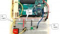
There are three sets of dual-in-line package (DIP) switches mounted on the FPK PCB. The first DIP switch has eight pre-built components wired to it. You will slide the first two switches labeled KEY1 and KEY2 to the ON position. Sliding these switches will electrically connect KEY1 and KEY2 to digital pins 2 and 3 of the FPK control board.
Once KEY1 and KEY2 are enabled, the blue and yellow buttons on the FPK, labeled as S1 and S2, will be the start and stop buttons for the latching circuit.
Repeat the same setup to enable the relay-controlled LED, which is electrically wired to digital pin 7 of the FPK control board. Figure 9 shows the DIP switches for KEY1, KEY2, and the Relay.

Figure 9. Enabling KEY1 and KEY2 DIP switches and the relay-controlled LED.
Pressing the S1 tactile pushbutton will turn on the relay-controlled LED but not latch it. To correct the switching function, change the DOWN_stop to a non-inverting (normal) bit instruction. Change the UP_start to an inverting (negated) bit instruction. Upload the revised LD program to the FPK control board. Pressing the S1 tactile pushbutton switch latches the relay-controlled LED. When you press the S2 tactile pushbutton switch, the LED turns OFF (unlatch). Congratulations on successfully building and programming an FPK PLC!

Figure 10. Correcting the Latching function of the Start-Stop Control LD program.
The following video clip will illustrate the final operation of the OpenPLC FPK Start-Stop Control LD program.
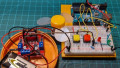
One major difference between this control automation development approach compared to previous OpenPLC projects is that no extra wiring is needed. Such an approach will allow PLC concepts to be rapidly developed and tested. Although the FPK may seem like a one-stop solution to prototyping PLC control automation concepts, there is a slight limitation which will be discussed in the next project article.
Interactive Quiz: Logic OR Gate Solution

Interactive Quiz:
Modify the FPK Start-Stop Control LD program where the Blue LED ([6]: D13) displays the latch/unlatch operation state.
Technical Quiz:
Explain why the DOWN_Stop and UP_Start bit instructions had to be inverted to correct the control circuit operation.
For more information about this Freenove Projects Kit (FPK) product and other available Arduino-compatible project kits, visit the Freenove store site.