Facebook
 Google
 GitHub
 Linkedin
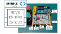
Count Up (CTU) Instructions on an Arduino OpenPLC Simulator
DC motors are an old technology still commonly used in industry. This hands-on article shows how to implement a Count Up (CTU) counter on an Arduino OpenPLC Simulator to control a low-voltage DC motor.
Check out the Arduino OpenPLC project articles:
Simplified Prototyping: OpenPLC on an Arduino-Compatible Project Kit
PLC Ladder Logic on an Arduino: Introduction to OpenPLC
PLC Ladder Logic on an Arduino: Building a Start-Stop Circuit
Counters with OpenPLC: Count Down Instructions on an Arduino Project Kit
In the last installment of our hands-on Arduino OpenPLC project series, we explored implementing a Count Down (CTD) counter using an Arduino-compatible prototyping board. The CTD Function Block (FB) is part of the IEC 61131-3 document on functional programming languages for PLCs. The IEC 61131-3 section on counters provides technical information on the various counters a control technician or engineer may use for implementing automation control applications. The information relevant to a control technician or engineer is the FB pin definition and the structure text listing for the counter. Figure 1 provides the CTD FB pin definitions for the programmable counter.
|
Parameter |
Data Types |
Description |
|
CU |
BOOL |
If a rising edge is detected, CV is increased by one. |
|
RESET |
BOOL |
If TRUE, the counter is initialized with 0. If FALSE, counting is enabled. |
|
PV |
INT |
Preset Value |
|
Q |
BOOL |
TRUE if CV >= PV |
|
CV |
INT |
Counter result |
Table 1. CTU FB pin definitions
Count Up (CTU) Function Block (FB) Primer
As observed, there are three Boolean (BOOL) data type pins and two integer data type (INT) pins. The BOOL data type pins will react to ON or OFF switch contact events, while INT data type pins are non-decimal numbers. With the pin definition table, the CTU FB tag I/O listing can easily be created for the specific control application.

Figure 1. The CTU FB with labeled pins.
The functional logic behind the CTU FB can be illustrated using the equivalent IEC 61131-3 Structured Text (ST) language format.

Figure 2. ST equivalent programming language for a CTU FB.
The ST format explains the operation of the CTU FB in text. The operation of the CTU FB is as follows:
-
If the Reset (R) is activated, the Current Value (CV) is equal to 0.
-
Else if the Count Up (CU) value and the CV are less than the maximum Preset Value (PVmax), the CV value is incremented.
-
The equation used to increment the CV is the counter equation of CV +1.
-
The CTU FB will end the counting event when the CV is greater than or equal to the PV. When the conditional equation is true, the CTU FB output (Q) is turned on.
Figure 3 shows the OpenPLC-generated ST program for a CTU FB.

Figure 3. OpenPLC Count Up ST program.
The ST file may be found within the generated OpenPLC file structure of the specified ladder diagram (LD) build folder. Figures 4 and 5 illustrate the locations of the Count Up counter LD application programmed in OpenPLC. The ST file is text-based; therefore, it can be viewed using any notepad or word processing software package.
 Figure 4. OpenPLC build folder.
 Figure 5. The ST text file location.
Creating the CTU Counter DC Motor Controller
With a fundamental understanding of the CTU FB, we may commence building a CTU-driven direct current (DC) motor controller. The hardware required to build this controller consists of using off-the-shelf components. Here is a list of the components required for this build:
-
(1) Arduino OpenPLC simulator
-
(1) L298N DC motor driver module
-
(1) 3-6 VDC motor
-
(1) 9 V battery
-
(1) 9 V battery snap with stranded lead wires
The Arduino OpenPLC simulator is essentially the LED indicators and tactile pushbutton switches wired to an Arduino Uno using a solderless breadboard. The assembly instructions to build the simulator may be obtained from the introductory article. The general concept of the motor controller hardware is illustrated in Figure 7.

Figure 6. Count Up Counter DC Motor controller prototype concept
To provide a system architecture perspective of the CTU counter DC motor controller, a block diagram is provided in Figure 8.

Figure 7. Count Up Counter DC Motor Controller Block Diagram
As illustrated in Figure 7, the enhancement made to the Arduino OpenPLC is the L298N DC motor driver module. This electronic control module is capable of operating two DC motors independently. Figure 7 illustrates that one control signal is required to operate the motor driver. Therefore, the module can easily be wired and operated using the OpenPLC simulator.
Preparing the L298N module consists of electrically attaching it to the Arduino, the DC power supplies, and a small DC motor. Figure 9 provides an electrical wiring diagram for attaching the 9 V battery, a +5 V DC voltage source, and motor to the module.

Figure 8. The L298N DC motor module electrical wiring diagram
An important item to observe is the IN1 attachment to digital pin 7 of the Arduino. The Arduino will provide a digital control signal voltage of approximately +5 V to the L298N H-Bridge device. Upon receiving this control signal voltage, the L298N integrated circuit (IC) will turn on the small motor wired to terminal pins OUT1 and OUT2 on the module. Figure 9 shows the complete attachment of the 9 V battery and the motor to the module.

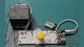
Figure 9. Complete small DC motor attached to the L298N module
Although the 5 V supply on the Arduino board can technically provide voltage to this very small motor, it is good industrial wiring practice to provide electromechanical devices with their own power sources. The demand for such components can exceed the current limits of the Arduino’s onboard 5 V regulated power supply requirements.
The final step to completing the hardware build is wiring the Arduino OpenPLC controller to the L298N motor driver. The wires that will be connected into the Arduino’s ‘Power’ and ‘Digital’ headers are the +5 VDC Supply, GND, and the Digital Pin 7 leads.
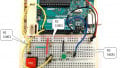
Figure 10 provides an I/O wiring diagram illustrating the location of the insertion points of the two wires to the Arduino female header connector. Notice that the Digital Pin 8 wire is electrically wired to resistor R4 (220Ω) mounted on the solderless breadboard.

Figure 10. The Arduino I/O wiring diagram
Figure 11 shows the complete build of the Count Up Counter DC Motor Controller prototype. The compactness of the build allows ease of transporting for technical training and demonstration, but you may also design a similar efficient form factor. The other benefit of this build is that another 9 V battery can be attached to the Arduino when the USB power is removed, thus providing an untethered device for education, technical training, and demonstration.

Figure 11. The assembled Count Up counter DC motor controller
CTU Counter Ladder Diagram
The Count Up software is a generic LD that allows the activation of one pushbutton to increment the CTU FB counter. The other pushbutton resets the CTU FB counter when the CV equals the PV. To understand the bit instructions and FB components for this counter application, refer to the previous article. The CTU FB counter in the OpenPLC Standard function block library is illustrated in Figure 12.

Figure 12. Selecting the CTU FB from the standard function block library
The next step is creating a tag I/O listing, which is explained in detail in the following article. Here is the tag I/O listing for this Count Up LD control software.

Figure 13. Count Up counter tag I/O listing
With the tag listing created, Figure 14 provides a look at the LD for the Count Up counter control software ladder diagram.

Figure 14. The Count Up counter LD
Operating the DC Motor Controller
With the CTU LD built, attach your Arduino to your computer using a USB cable. Select the Arduino icon viewed on the OpenPLC task bar. Your control’s development platform monitor screen will display a setup window. Select the appropriate communication (COM) port within the setup window. Select the upload button with your mouse, and within a few minutes, the output window will display Done.
The ‘Ready’ LED will be illuminated. Press the ‘Count Up’ button ten times: the Ready LED will turn off and the motor will turn on while the ‘Complete’ LED will be illuminated.
Pressing the ‘Reset’ button will turn off the Complete LED and the motor. The Ready LED will be turned on.
Here is a video clip of the motor controller and program in operation:
Congratulations on building your counter-driven DC motor controller. Next time, the Arduino OpenPLC simulator counter-control experience will be enhanced using an industrial photoelectric switch.
Interactive Quiz
Using the truth table provided, redraw Figure 10 showing the L298N DC Motor Driver Module operating the small DC motor in the reverse direction.

Interactive Quiz: L298N DC motor driver module truth table