Facebook
 Google
 GitHub
 Linkedin
Methods of Performing Robot Tool Center Point Calibration
Industrial robots are a valuable investment because of their speed and accuracy. However, failing to establish the tool center point (TCP) can decrease the accuracy, effectiveness, and ROI for a robot workcell.
With any robot application, there will be a tool mounted on the end of the robot arm. This tool allows the robot to manipulate objects in the physical world. In order for the robot to know where that tool is with respect to the base coordinate system, there needs to be a TCP defined. For any manipulation of the tool, such as an angle rotation, the movement must be centered around the very end of the tool—perhaps a gripper or welder. If this center point is not defined exactly, rotational adjustments will move the tooltip, rather than simply rotating it as desired.
Robot Tool Center Point (TCP) Defaults
The default TCP is at the center of the mounting face plate and flush with the face plate. Some tools do not require adjusting the default TCP dimensions but it is recommended by most robot manufacturers to create custom TCPs. A well-defined TCP is especially critical when jogging in difficult positions and with specific offsets using odd shaped tools.

Figure 1. The default TCP is flush with the mounting plate of the robot gripper. Image courtesy of ABB
Calibrating The Tool Center Point
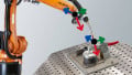
The purpose of calibrating the TCP is to provide the exact position and orientation of the tooltip, referenced from the base of the robot which is known as the base coordinate system. An industry standard for calibrating a TCP involves teaching three or four positions around a single point but at different orientations and using the software supplied by the robot manufacturer to calculate the position of the TCP.
To aid this calibration process, equipment builders will sometimes design special tools that fix onto the end effector in place of, or alongside the actual tool. These calibration tools are typically very sharp points with very long lead-ins and have a matching point that is fixed somewhere on a solid surface. The two sharp points allow the technician to accurately see if the points are aligned precisely. In order to make this process as accurate as possible, the X, Y, and Z locations of each position should be exactly the same; the only difference between each position should be the configuration of the robot arm, sometimes called the ‘approach’ to the point. This process can sometimes be time-consuming and require multiple tries.

Figure 2. Multiple approach paths to the TCP will allow the software to calculate the exact point by triangulation. Image courtesy of ABB
Calibrating Process
With any robot software, there are at least three different orientation options for calibrating your TCP manually, and a final method for direct entry.
-
Default TCP Orientation
Sometimes called the 3-point method, this orientation keeps the same rotation as the default center point but allows the programmer to define a new location for that center point. A typical gripper or vacuum system, which is aligned perfectly parallel to the original mounting face, does not require any angular change. Instead, it only requires a shift in position for the TCP.
-
TCP&Z
With this option, you can set the orientation by teaching an additional position to define the z-axis, which will move the tool closer or away from the workpiece. Typically when using this method, the final teach motion should jog the robot only in the z-axis, which is directly away from the teaching tool. This option will set which way Z+ will be oriented with the x-axis and y-axis to follow.
-
TCP&Z, X
This method is sometimes called the six-point method. If you want to make sure your x-axis and z-axis (and therefore the final y-axis as well) are in a specific orientation, use this option to ensure you get the results you require. Much like the TCP&Z option, two additional positions will be required to be taught making sure to only move either z-axis or x-axis.
-
Direct Positional Data Entry
When CAD data is available for a custom tool, or if exact measurements can be obtained, the X, Y, and Z, as well as any angular data, can be directly entered into the TCP setup, which removes any need for navigating the robot to a number of approach points.
The number of positions is selectable but typically only four positions are required for an accurate TCP. More than four positions can be selected to increase the accuracy of the TCP, but all positions will require the same level of detail when defining each position. The idea is to keep the X, Y, and Z position the same but only change the robot configuration with each position that is taught.
To perform this calibration process, simply jog the robot into position carefully aligning the tool point and the fixed point. It is reasonable to start consistently with a position that brings the tool down from the top at 90 degrees to the fixed point.
For the second position, raise the robot up and then rotate the tool in order to approach the teach point at an angle as close to 90 degrees as possible from the first point. Then, carefully make the two points touch. Finally, repeat this process by jogging the robot from another 90 degree approach at a time until all four positions have been taught. For the last position, try to end up at 90 degrees to the fixed point again so that the Z orientation position will be directly above the fixed point.

Figure 3. Using four points to identify not only the TCP location, but also rotational orientation. Image used courtesy of ABB

Figure 4. Comparing an original (0) and a new (1) TCP, in this case with only location change—the orientation has remained the same. Image used courtesy of ABB
Manually Entering TCP Dimensional Values
Sometimes the end effector is too big or there is not enough room within the machine to accurately define the TCP using those various approach paths. Some robot styles cannot accommodate this method of calibrating, such as SCARA, gantry, or delta robots, which can only approach the pick point from a single direction. In this situation, we need to manually measure and enter the position of the TCP, as briefly mentioned earlier. 3D modeling software can assist with this process but should not be substituted for actually measuring the position of the TCP.
When measuring the tool, you do not need to measure all the way to the base of the robot, only to the mounting flange of the tool. When measuring, make sure you are taking measurements from the center and the mounting surface of the flange. As the measurements are recorded, they can be entered into the teach pendant in their respective registers. Even if you have used the above calculation method, you can always tweak the tool data from the tool datatype if you find a slight error when jogging the robot.

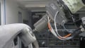
Figure 5. RoboDK’s Twin Tool is an easily-integratable, automated TCP that uses a linear sensor gauge to guide the robot into different positions. Image courtesy of RoboDK
Automated Method of Calibration for TCP
Today, there are some manufacturers that have come up with an automated or semi-automated method. RoboDK’s Twin Tool uses a linear sensor gauge to detect the robot’s tool in different positions. The software will guide the robot into multiple positions taking the human error out of the equation. Leoni is another manufacturer that offers a calibration aid system. The advintec TCP calibration system makes use of horseshoe-style through-beam sensors to detect the location of the tool.
Robot TCP Calibration
There are many different methods to calibrate a TCP, and they all have their benefits and defects. Whichever method you choose, it is important to ensure the accuracy of both the location and the angular orientation of the TCP. If these are not accurate, all performance metrics of the robot system may be invalidated simply because of a calibration process, so it is important to handle this step with care.