 Facebook
 Google
 GitHub
 Linkedin
Pneumatic PID Controllers

Variable air pressure can be used as a signal in pneumatic ‘control circuits’ to provide P, I, and D responses, each with gain values controlled by valves or mechanical components.
A pneumatic controller receives a process variable (PV) signal as a variable air pressure, compares that signal against a desired setpoint (SP) value, and then mechanically generates another air pressure signal as the output, driving a final control element.
Throughout this section, I will make reference to a pneumatic controller mechanism of my own design. This mechanism does not directly correspond to any particular manufacturer or model of pneumatic controller, but shares characteristics common to many. This design is shown here for the purpose of illustrating the development of P, I, and D control actions in as simple a context as possible.
Pneumatic Controller - Proportional Control
Force-Balance Principle
Many pneumatic PID controllers use the force-balance principle. One or more input signals (in the form of pneumatic pressures) exert a force on a beam by acting through diaphragms, bellows, and/or bourdon tubes, which is then counter-acted by the force exerted on the same beam by an output air pressure acting through a diaphragm, bellows, or bourdon tube. The self-balancing mechanical system “tries” to keep the beam motionless through an exact balancing of forces, the beam’s position precisely detected by a nozzle/baffle mechanism:

The action of this particular controller is direct, since an increase in process variable signal (pressure) results in an increase in output signal (pressure). Increasing process variable (PV) pressure attempts to push the right-hand end of the beam up, causing the baffle to approach the nozzle. This blockage of the nozzle causes the nozzle’s pneumatic backpressure to increase, thus increasing the amount of force applied by the output feedback bellows on the left-hand end of the beam and returning the flapper (very nearly) to its original position. If we wished to reverse the controller’s action, all we would need to do is swap the pneumatic signal connections between the input bellows, so that the PV pressure was applied to the upper bellows and the SP pressure to the lower bellows.
Gain Adjustment for Pneumatic Force-Balance
Any factor influencing the ratio of input pressure(s) to output pressure may be exploited as a gain (proportional band) adjustment in this mechanism. Changing bellows area (either both the PV and SP bellows equally, or the output bellows by itself) would influence this ratio, as would a change in output bellows position (such that it pressed against the beam at some difference distance from the fulcrum point). Moving the fulcrum left or right is also an option for gain control, and in fact is usually the most convenient to engineer.
In this illustration the fulcrum is shown moved to two different positions, to effect a change in gain:

Moving the fulcrum closer to the output bellows places that bellows at a mechanical disadvantage for generating torque (leverage) on the beam. This means any given change in input (PV or SP) force is more difficult for the output bellows to counterbalance. The output pressure, therefore, must change to a greater degree in order for this force-balance mechanism to achieve balance. A greater change in output pressure for a given change in input pressure is the definition of a gain increase.
Conversely, moving the fulcrum farther away from the output bellows increases that bellows’ mechanical advantage. This additional leverage makes it easier for the output bellows to counter-act changes in input force, resulting in less output pressure change required to balance any given input pressure change. A lesser change in output pressure for a given change in input pressure is characteristic of a gain decrease.
Motion-Balance Principle
Some pneumatic controllers employ the motion-balance principle instead of the force-balance principle in their operation. In contrast to a force-balance system where opposing forces cancel each other to restrain motion of the mechanism, a motion-balance system freely moves as the signal pressures traverse their working ranges. A simple motion-balance proportional controller design appears here:

As the process variable signal increases, the right-hand end of the lever is forced up. This motion draws the lever away from the nozzle, resulting in decreased nozzle backpressure. The decreased backpressure causes the output bellows to collapse, moving the left-hand end of the lever down and returning the nozzle/lever gap to (approximately) where it was before the PV signal change. This behavior identifies this controller as reverse-acting. If direct action were desired, all we would need to do is swap the process variable and setpoint input pressure connections.
Unlike the force-balance controller mechanism where the lever is maintained in an essentially stationary position by equal and opposite forces, the lever in this motion-balance system is free to tilt. In fact, tilting is precisely how a (nearly) constant nozzle gap is maintained: as one end of the lever moves (either up or down), the other end moves in the opposite direction to keep the nozzle/lever gap constant in the middle.
Gain Adjustment for Pneumatic Motion-Balance
The gain of such a mechanism may be changed by moving the position of the nozzle along the lever’s length. However, it must be understood that this position change will have the opposite effect on gain compared with the fulcrum position change described for the force-balance mechanism. Here in the motion-balance system, it is the relative travel of each bellows that matters for gain, not the relative leverage (torque):

With the nozzle positioned closer to the output bellows, that bellows need not stretch or collapse as much in order to maintain the nozzle gap constant even with a large motion at the input (right-hand) end of the lever. The output pressure in this case will change only slightly for large changes in PV or SP pressures: characteristic of a low gain.
Moving the nozzle closer to the input (PV and SP) bellows gives those bellows more influence over the nozzle/lever gap. The output bellows must expand and contract quite a bit more than the input bellows in order to maintain a constant nozzle gap for any motion at the input side. This requires a greater change in output pressure for a given change in input pressure: the definition of increased gain.
Automatic and Manual Modes
A more practical pneumatic proportional controller mechanism is shown in the next illustration, complete with setpoint and bias adjustments, and a manual control mode:

Bumpless Transfer
“Bumpless” transfer between automatic and manual modes is a very important feature for any loop controller because it allows human operators to change the mode of the controller without introducing an unnecessary disturbance to the process being controlled. Without provision for bumpless transfer, the output signal of the controller may suddenly change whenever the mode is switched between automatic and manual. This sudden signal change will cause the final control element to suddenly “step” to some new level of effect on the process.
In this particular pneumatic controller, bumpless auto/manual transfer is accomplished by the operator paying attention to the balance indicator revealing any air pressure difference between the output bellows and the output adjust pressure regulator. When in automatic mode, a switch to manual mode involves adjusting the output regulator until the balance indicator registers zero pressure difference, then switching the transfer valve to the “manual” position. The controller output is then at the direct command of the output adjust pressure regulator, and will not respond to changes in either PV or SP. “Bumplessly” switching back to automatic mode requires that the setpoint pressure regulator be adjusted until the balance indicator once again registers zero pressure difference, then switching the transfer valve to the “auto” position. The controller output will once again respond to changes in PV and SP.
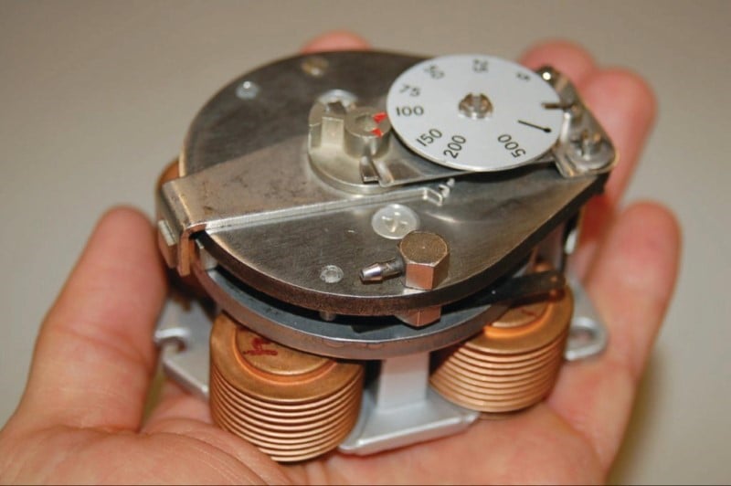
A photograph showing a Foxboro model 43AP pneumatic controller manual/auto transfer switch and balance indicator appears here:

The metal ball within the curved plastic tube indicates equal pressures between automatic and manual modes when centered in the tube. To achieve bumpless transfer between automatic and manual modes, one must never switch the auto/manual valve unless that ball is centered. To center the ball while in automatic mode, the manual output pressure must be adjusted to achieve balance with the automatic-mode output pressure. To center the ball while in manual mode, the automatic-mode output pressure must be adjusted to achieve balance with the manual-mode output pressure – a condition attained by adjusting the setpoint knob.
Pneumatic Derivative Controller Action
Derivative (rate) control action is relatively easy to add to this pneumatic controller mechanism. All we need to do is place a restrictor valve between the nozzle tube and the output feedback bellows, causing the bellows to delay filling or emptying its air pressure over time:

If any sudden change occurs in PV or SP, the output pressure will saturate before the output bellows has the opportunity to equalize in pressure with the output signal tube. Thus, the output pressure “spikes” with any sudden “step change” in input: exactly what we would expect with derivative control action.
If either the PV or the SP ramps over time, the output signal will ramp in direct proportion (proportional action), but there will also be an added offset of pressure at the output signal in order to keep air flowing either in or out of the output bellows at a constant rate to generate the force necessary to balance the changing input signal. Thus, derivative action causes the output pressure to shift either up or down (depending on the direction of input change) more than it would with just proportional action alone in response to a ramping input: exactly what we would expect from a controller with both proportional and derivative control actions.
Pneumatic Integral Controller Action
Adding integral action to our hypothetical pneumatic controller mechanism requires the placement of a second bellows (a “reset” bellows) opposite the output feedback bellows, and another restrictor valve to the mechanism:

This second bellows takes air pressure from the output line and translates it into force that opposes the original feedback bellows. At first, this may seem counter-productive, for it nullifies the ability of this mechanism to continuously balance the force generated by the PV and SP bellows. Indeed, it would render the force-balance system completely ineffectual if this new “reset” bellows were allowed to inflate and deflate with no time lag. However, with a time lag provided by the restriction of the integral adjustment valve and the volume of the bellows (a sort of pneumatic “RC time constant”), the nullifying force of this bellows becomes delayed over time. As this bellows slowly fills (or empties) with pressurized air from the nozzle, the change in force on the beam causes the regular output bellows to have to “stay ahead” of the reset bellows action by constantly filling (or emptying) at some rate over time.
To better understand this integrating action, let us perform a “thought experiment” on a simplified version of the controller. The following mechanism has been stripped of all unnecessary complexity so that we may focus on just the proportional and integral actions. Here, we envision the PV and SP air pressure signals differing by 3 PSI, causing the force-balance mechanism to instantly respond with a 3 PSI output pressure to the feedback bellows (assuming a central fulcrum location, giving a controller gain of 1). The reset (integral) valve has been completely shut off at the start of this thought experiment:

With 0 PSI of air pressure in the reset bellows, it is as though the reset bellows does not exist at all. The mechanism is a simple proportional-only pneumatic controller.
Now, imagine opening up the reset valve just a little bit, so that the output air pressure of 3 PSI begins to slowly fill the reset bellows. As the reset bellows fills with pressurized air, it begins to push down on the left-hand end of the force beam. This forces the baffle closer to the nozzle, causing the output pressure to rise. The regular output bellows has no restrictor valve to impede its filling, and so it immediately applies more upward force on the beam with the rising output pressure. With this greater output pressure, the reset bellows has an even greater “final” pressure to achieve, and so its rate of filling continues.
The result of these two bellows’ opposing forces (one instantaneous, one time-delayed) is that the lower bellows’ pressure must always lead 3 PSI ahead of the upper bellows’ pressure in order to maintain a pressure difference of 3 PSI necessary to balance force with the PV and SP bellows (whose pressures differ by 3 PSI). This creates a constant 3 PSI differential pressure across the reset restriction valve, resulting in a constant flow of air into the reset bellows at a rate determined by that pressure drop and the opening of the restrictor valve. Eventually this will cause the output pressure to saturate at maximum, but until then the practical importance of this rising pressure action is that the mechanism now exhibits integral control response to the constant error between PV and SP:

The greater the difference in pressures between PV and SP (i.e. the greater the error), the more pressure drop will develop across the reset restriction valve, causing the reset bellows to fill (or empty, depending on the sign of the error) with compressed air at a faster rate, causing the output pressure to change at a faster rate. Thus, we see in this mechanism the defining nature of integral control action: that the magnitude of the error determines the velocity of the output signal (its rate of change over time, or \(dm \over dt\)). The rate of integration may be finely adjusted by changing the opening of the restrictor valve, or adjusted in large steps by connecting capacity tanks to the reset bellows to greatly increase its effective volume.
Example Pneumatic Controller PI System: Fisher MultiTrol
Front (left) and rear (right) photographs of a real pneumatic controller (a Fisher “MultiTrol” unit) appear here:
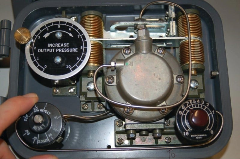

The mechanism is remarkably similar to the one used throughout the explanatory discussion, with the important distinction of being motion-balance instead of force balance. Proportional and integral control modes are implemented through the actions of four brass bellows pushing as opposing pairs at either end of a beam:

The nozzle may be seen facing down at the middle of the beam, with the center of the beam acting as a baffle. Setpoint control is achieved by moving the position of the nozzle up and down with respect to the beam. A setpoint dial (labeled “Increase Output Pressure”) turns a cam which moves the nozzle closer to or farther away from the beam. This being a motion-balance system, an offset in nozzle position equates to a biasing of the output signal, causing the controller to seek a new process variable value.
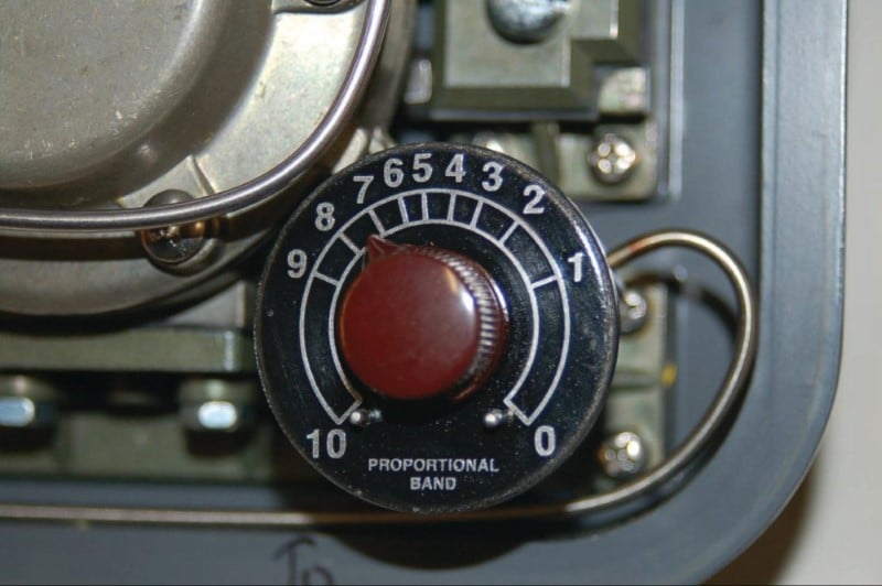
Instead of altering the position of a fulcrum to alter the gain (proportional band) of this controller, gain control is effected through the use of a “pressure divider” valve proportioning the amount of output air pressure sent to the feedback bellows. Integral rate control is implemented exactly the same way as in the hypothetical controller mechanism illustrated in the discussion: by adjusting a valve restricting air flow to and from the reset bellows. Both valves are actuated by rotary knobs with calibrated scales. The reset knob is actually calibrated in units of minutes per repeat, while the proportional band knob is labeled with a scale of arbitrary numbers:

Selection of direct versus reverse action is accomplished in the same way as selection between proportional and snap-action (on-off) control: by movable manifolds re-directing air pressure signals to different bellows in the mechanism. The direct/reverse manifold appears in the left-hand photograph (the letter “D” stands for direct action) while the proportional/snap manifold appears in the right-hand photograph (the letter “P” stands for proportional control):
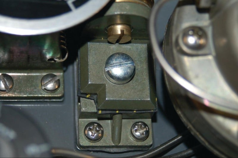

Either setting is made by removing the screw holding the manifold plate to the controller body, rotating the plate one-quarter turn, and re-attaching. The following photograph shows one of the manifold plates removed and turned upside-down for inspection of the air passages:

The two quarter-circumference slots seen in the manifold plate connect adjacent air ports together. Rotating the plate 90 degrees connects the four air ports together as two different pairs.
Example Pneumatic PI System: Foxboro 43AP
The Fisher MultiTrol pneumatic controller is a very simple device, intended for field-mounting near the pneumatic transmitter and control valve to form a control loop for non-precision applications. A more sophisticated field-mounted pneumatic controller is the Foxboro model 43AP, sporting actual PV and SP indicating pointers, plus more precise tuning controls. The following photographs show one of these controllers, with the access door closed (left) and open (right):


At the heart of this controller is a motion-balance “pneumatic control unit” mechanism. A dial for setting proportional band (and direct/reverse action) appears on the front of the mechanism:


Note the simple way in which direct and reverse actions are described on this dial: either increasing measurement, decreasing output (reverse action) or increasing measurement, increasing output (direct action).
Example Pneumatic PID Controller: Foxboro 130
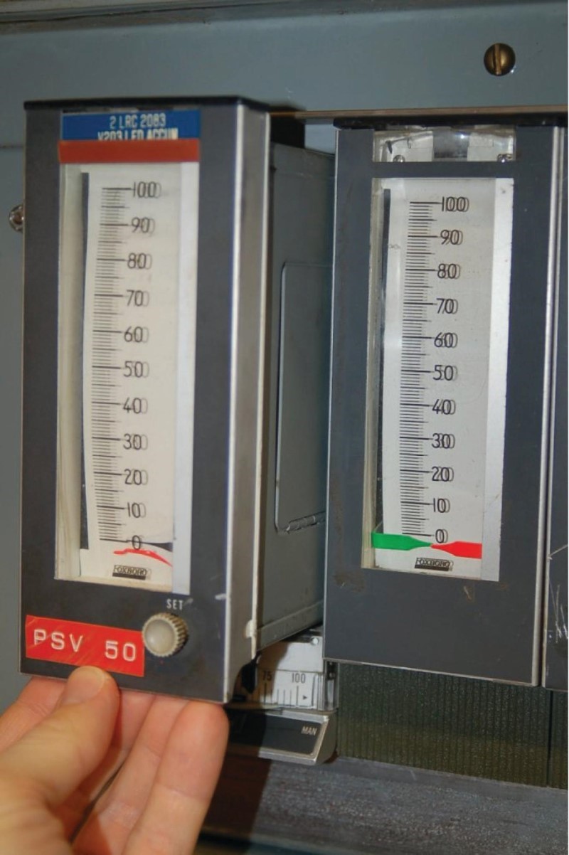
Foxboro also manufactured panel-mounted pneumatic controllers, the model 130 series, for larger-scale applications where multiple controllers needed to be located in one compact space. A bank of four Foxboro model 130 pneumatic controllers appears in the next photograph:

Each controller may be partially removed (slid out) from its slot in the rack, the P, I, and D settings adjustable on the left side panel with a screwdriver:

With the side panel removed, the entire mechanism is open to viewing:

The heart of the model 130 controller is a four-bellows force-balance mechanism, identical in principle to the hypothetical force-balance PID controller mechanism used throughout the explanatory discussion. Instead of the four bellows acting against a straight beam, however, these bellows push against a circular disk:

A nozzle (shown in the next photograph) detects if the disk is out of position (unbalanced), sending a back-pressure signal to an amplifying relay which then drives the feedback bellows:

The disk rocks along an axis established by a movable bar. As this bar is rotated at different angles relative to the face of the disk, the fulcrum shifts with respect to the four bellows, providing a simple and effective gain adjustment:

If the moment arms (lever lengths) between the input (PV and SP) bellows and the feedback bellows are equal, both sets of bellows will have equal leverage, and the gain will be one (a proportional band setting of 100%). However, if the fulcrum bar is rotated to give the input bellows more leverage and the feedback bellows less leverage, the feedback bellows will have to “work harder” (exert more force) to counteract any imbalance of force created by the input (PV and SP) bellows, thus creating a greater gain: more output pressure for the same amount of input pressure.
The fourth (lower-left) bellows acting on the disk provides an optional reset (integral) function. Its moment arm (lever length) of course is always equal to that of the feedback bellows, just as the PV and SP bellows’ moment arm lengths are always equal, being positioned opposite the fulcrum line.
Selection between direct and reverse action works on the exact same principle as in the Fisher MultiTrol controller – by connecting four air ports in one of two paired configurations. A selector (movable with a hex wrench) turns an air signal port “switch” on the bottom of the four-bellows unit, effectively switching the PV and SP bellows:


An interesting characteristic of most pneumatic controllers is modularity of function: it is possible to order a pneumatic controller that is proportional-only (P), proportional plus integral (P+I), or full PID. Since each control mode requires additional components to implement, a P-only pneumatic controller costs less than a P+I pneumatic controller, which in turn costs less than a full PID pneumatic controller. This explains the relative scarcity of full PID pneumatic controllers in industry: why pay for additional functionality if less will suffice for the task at hand?
External Reset Integral Feedback
Some pneumatic controllers come equipped with an option for external reset: a feature useful in control systems to avoid integral windup if and when the process stops responding to changes in controller output. Instead of receiving a pneumatic signal directly from the output line of the controller, the reset bellows receives its signal through another pneumatic line, connected to a location in the control system where the final effect of the output signal (\(m\)) is seen. If for some reason the final control element cannot achieve the state called for by the controller, the controller will sense this through the external reset signal, and will cease integration to avoid “wind-up.”
In the following illustration, the external reset signal comes from a pneumatic position transmitter (ZT) mounted to the sliding stem of the control valve, sending back a 3-15 PSI signal representing valve stem position:

If something happens to the control valve causing it to freeze position when the controller commands it to move – suppose the stem encounters a mechanical “stop” limiting travel, or a piece of solid material jams the valve trim so it cannot close further – the pneumatic pressure signal sent from the position transmitter to the controller’s reset bellows will similarly freeze. After the pneumatic lag caused by the reset restrictor valve and bellows passes, the reset bellows force will remain fixed. This halts the controller’s integral action, which was formerly based on a “race” between the output feedback bellows and the reset bellows, causing the feedback bellows to “lead” the reset bellows pressure by an amount proportional to the error between PV and SP. This “race” caused the output pressure to wind either up or down depending on the sign of the error. Now that the reset bellows pressure is frozen due to the control valve stem position being frozen, however, the “race” comes to an end and the controller exhibits only proportional action. Thus, the dreaded effect of integral windup – where the integral action of a controller continues to act even though the change in output is of no effect on the process – is averted.
REVIEW:
-
Pneumatic proportional control is achieved with the fulcrum point adjustment of a force- or motion-balance lever which opens or closes a nozzle, lowering or raising the outlet pressure, much like a pressure regulator.
-
Pneumatic derivative control is the addition of a flow restriction to the proportional balance lever mechanism, providing finite control over the lever’s responsiveness to rapid rate changes in input.
-
Pneumatic integral control requires a restricted flow opposing the balance lever, which will provide a resistive force lagging behind the output, accumulating the resistive force while the pressure is imbalanced (error).
Interested in more PID and control system topics?
Related Worksheets:
- PID loop tuning
- Troubleshooting problems in control systems
- RTD and thermocouple circuits with millivolt calculations
Related Textbook Pages:
- Negative Consequences of Poor PID Controller Tuning
- Tuning PID Controllers
- Logic Programming in PLCs
Related Technical Articles:
- Using PID and Feedback Loops for Precise Motion Systems
- Proportional Gain and Proportional Band Explained
- Integral Windup Method in PID Control

The best explanation ever!
Good illustration