Facebook
 Google
 GitHub
 Linkedin
Reversing Motor Contactors: Interlocking Methods That Prevent Short-Circuits
Installing a reversing contactor is only half the project; ensuring safety and reliable performance under load is a top priority for motor control designs.
Reversing contactor circuits are used wherever a three-phase motor must run in both directions: conveyors, hoists, doors, positioning systems, pumps, and material-handling equipment. One contactor connects the motor for forward rotation, while a second contactor swaps two of the phases to reverse the sequence.
The arrangement is familiar, but its failures can be severe. A wiring error, defeated interlock, or welded contact may allow both contactors to close together. Because the reverse contactor intentionally crosses two phases, overlapping operations can short-circuit opposing phases directly through the contactor poles. The likely result is an immediate breaker or fuse trip, severe arcing, damaged contacts, or burned conductors.
Some faults are obvious during startup. Others appear only during rapid direction changes, maintenance mode, or remote operation. A secure design must also prevent faults when wiring is altered or a component fails.
How Does a Reversing Contactor Work?
A standard reversing starter uses 2x three-pole contactors. The forward device connects L1, L2, and L3 straight to the motor in the normal sequence. The reverse device changes the connection of two phases, often L1 and L3, causing the motor to rotate in the opposite direction.
If both contactors close, the crossed wiring can place one phase directly across another. This is not a conventional motor overload. It is a low-impedance phase-to-phase fault.
A mechanical interlock physically prevents one contactor from closing while the other is engaged. It may use a sliding bar, linkage, or integrated mechanism and remains effective regardless of PLC state.
Electrical interlocking provides a second layer. A normally closed auxiliary contact from the forward contactor is wired in series with the reverse coil. A normally closed auxiliary contact from the reverse contactor is wired in series with the forward coil. Energizing either contactor opens the control path to the other.
Auxiliary contacts may also provide seal-in logic, permissives, or status feedback. Schematics should distinguish those functions from the reversing interlock.
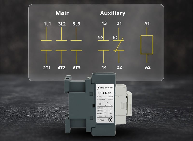
Figure 1. Wiring diagram of a three‑pole contactor used as part of a reversing starter, showing the main poles, integrated NO and NC auxiliary contacts, and the A1/A2 coil terminals. Image used courtesy of Contactor Depot
Common Failure Modes and Troubleshooting Stories
The following scenarios illustrate some of the common problems that plague reversing contactors.
The Mechanical Interlock is Missing
A conveyor’s original contactors are replaced with devices that fit the panel but do not accept the existing mechanical interlock. The machine runs normally in each direction during separate tests. It trips only when the operator commands reverse before the forward contactor has fully released.
Start with a visual inspection. Confirm that the interlock is installed, properly engaged, and compatible with both contactor frames. With motor power removed, attempt to press each armature manually. Closing one contactor should physically block the other.
The root cause is not simply a quick operator command. The circuit allowed a normal action to create overlapping closure. A timer may reduce the probability, but the correction is a compatible mechanical interlock.
A Control Path Bypasses the Electrical Interlock
A hoist works correctly from its local pushbuttons but blows a control fuse or trips upstream protection from a remote station. Measurements show control voltage across both coils during one command.
Compare the local and remote branches. Measure across each coil, then verify both NC auxiliary contacts with control power removed.
A common cause is a remote switch or PLC output connected downstream of the hardwired interlock contact, allowing the remote circuit to energize the coil directly. Every path capable of energizing either coil must pass through the opposite contactor’s NC auxiliary contact.
Manual Mode Defeats the Logic
A packaging machine operates reliably in automatic mode but trips intermittently during setup. The fault occurs while technicians use a maintained forward/reverse selector.
Continuity testing shows that the automatic branch includes electrical interlocking, while the manual branch feeds the coils directly. The designer relied on the selector switch to prevent simultaneous commands. That assumption fails if the wrong contact block is installed, the switch is misindexed, or its contacts overlap during transition.
Test every selector position, verify break-before-make action, and trace both manual outputs through the circuit. Interlocking that exists only in automatic mode is incomplete.
Welded or Loose Power Contacts
A reversing pump starter trips when changing from forward to reverse even though its mechanical and electrical interlocks appear correct. With power removed, one forward contactor pole still shows continuity.
A welded main contact can remain closed after the coil and armature release. When the reverse contactor closes, the stuck pole creates an unintended phase connection. Isolate the starter and check continuity through every main pole. Inspect for uneven wear, discoloration, or damage from previous faults.
Loose terminals can cause single-phasing, slow acceleration, overheating, or nuisance overload trips. Compare motor current in both directions and inspect the crossed conductors closely. Abnormal current in only one direction often points to a termination or damaged pole on that contactor.
Designing Safer Interlocks: Mechanical Plus Electrical
Reliable reversing circuits use both mechanical and electrical interlocks. The mechanical interlock prevents both contactors from closing simultaneously, while the electrical interlock blocks one coil whenever the opposing contactor is energized.
Wire each contactor’s normally closed auxiliary contact in series with the opposite coil. All control paths, including pushbuttons, PLC outputs, remote stations, and maintenance controls, should all pass through these interlocks.
For applications with frequent direction changes, add a stop delay or zero-speed permissive to reduce plugging current and mechanical stress. This supplements, but does not replace, hardwired interlocking.
Schematics should clearly identify the mechanical linkage and associate each auxiliary contact with its contactor coil.
Ratings, Overloads, and Application Notes
Interlocking cannot compensate for an undersized or incorrectly applied contactor. Select the devices according to motor horsepower, full-load current, utilization category, operating voltage, duty cycle, and expected starting and reversing frequency.
A conveyor that reverses twice per shift imposes a different contact duty than a positioning table that jogs hundreds of times per hour. Frequent starting, plugging, and reversing can shorten contact life even when the motor’s steady-state current is below the contactor’s nominal rating.
For a more detailed explanation of these selection factors, engineers can refer to “How to Size a Contactor for Motor Applications: A Complete Guide for Reliability and Safety”
Thermal overload protection should be sized for the motor current and arranged to protect the motor in both directions. Many IEC reversing starters use one overload relay installed downstream of the forward and reverse contactor pair. This arrangement allows the same overload relay to monitor motor current regardless of the selected direction.
Upstream fuses or a circuit breaker must be coordinated with the contactors and overload relay so that short-circuit and overload protection perform separate, predictable functions. The overload relay protects against sustained motor overcurrent. The upstream protective device must interrupt high-level faults, including a phase-to-phase short created by simultaneous contactor closure.
An industrial hoist might use an IEC forward/reverse contactor pair, a mechanical interlock, normally closed auxiliary electrical interlocks, and one shared thermal overload relay. Because hoists may reverse frequently under high starting torque, the design should also account for braking, plugging duty, mechanical load, and an enforced delay between directions.
A light commercial fan or pump may use a compact or definite-purpose contactor arrangement. The current may be lower, but pole configuration, motor rating, coil voltage, auxiliary-contact availability, and interlocking remain just as important. A small motor can still produce destructive fault current if two crossed phase paths close simultaneously.
Engineers often source IEC motor and reversing contactors, mechanical interlocks and auxiliary contact blocks, thermal overload relays, and definite-purpose contactors for light commercial or HVAC applications. For reversing service, the paired contactors and interlock accessories must be approved to work together; matching current and coil ratings alone is not enough.
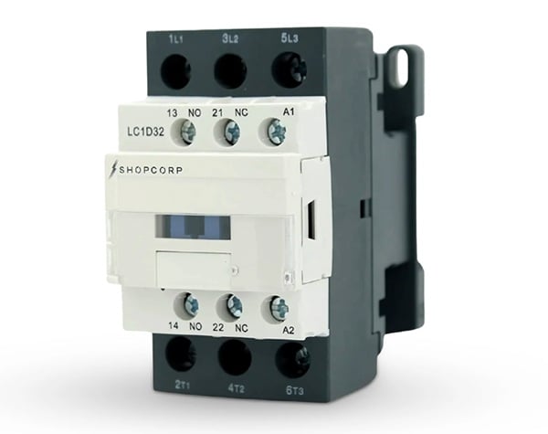
Figure 2. Example of a three-pole contactor with integrated auxiliary contacts. A complete reversing starter requires two compatible contactors together with mechanical and electrical interlocking. Image used courtesy of Contactor Depot
Practical Checklist for Engineers and Technicians
When reviewing, commissioning, or troubleshooting a reversing contactor circuit:
- Confirm that both contactors are mechanically compatible and interlocked.
- Verify the crossed phase conductors against the schematic.
- Ensure every coil command path passes through the opposite NC auxiliary contact.
- Test local, remote, automatic, and manual modes separately.
- Confirm selector switches use the required break-before-make action.
- Measure voltage directly across both coils during direction changes.
- With power isolated, verify that both contactors cannot close together.
- Check every main pole for welded contacts or unexpected continuity.
- Compare motor current in forward and reverse operation.
- Confirm contactor, overload, and upstream protection ratings for the actual reversing duty.
A reversing starter is dependable only when its safeguards remain effective during normal operation, maintenance activity, wiring errors, and component failure. Mechanical and electrical interlocks provide the foundation. Clear schematics, correct ratings, and disciplined commissioning keep that protection intact in the field.