Facebook
 Google
 GitHub
 Linkedin
Siemens TIA Portal and S7-1200 Tutorial 2: Analog Inputs
Programming simple coil and contact commands is an easy matter in most PLC IDEs. Connecting and configuring analog inputs can be more challenging with various bit resolutions and conversion commands.
Check Out the First of Our Siemens TIA Portal and S7-1200 Tutorials:
Intro to Siemens S7-1200 PLC and TIA Portal Programming
In a previous tutorial, we investigated the process of designing a new project in Siemens’s TIA Portal, then connecting and downloading a simple program to the S7-1200 PLC platform, illustrating a few simple coil and contact commands.
Rarely does an industrial system rely exclusively on discrete on/off signals, so the natural second level of understanding should include analog signals.
Analog inputs bring data from sensors, such as temperature, pressure, or set points from variable resistors.

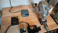
Figure 1. The Siemens S7-1200 PLC contains many built-in I/O points but can be expanded with modules of all kinds.
Analog outputs are a bit less common in the modern world of high-speed digital networking but are often still used to transmit specific variable signals to motion drivers and process control modules. Analog outputs will be covered in the next tutorial installment.
Analog Inputs
To understand inputs to the S7-1200 platform, we will first look at the wiring, then discuss the programming required to interpret the voltage at the terminal into a memory-mapped variable.
Analog Input Terminal Wiring
In the built-in analog channels for this PLC, the 0-10 V range is the permanent configuration for inputs. If the desired sensor or original device is a 4-20 mA current signal, there are modules and signal boards designed for such current signals.
Located at the top right corner of the PLC is a set of three analog terminals, 2M, 0, and 1. As expected, 0 and 1 are the analog voltage signal inputs, but the 2M is the common ground. If the inputs are measured with respect to the (-) 24 V rail, then this 2M terminal should also be connected to the common (-) 24 V rail.
For this example, a simple 1 kΩ potentiometer (3 terminal adjustable resistor) is configured with a 1.5 kΩ resistor in series with the 24 V supply to ensure that the variable voltage never exceeds 10 V.
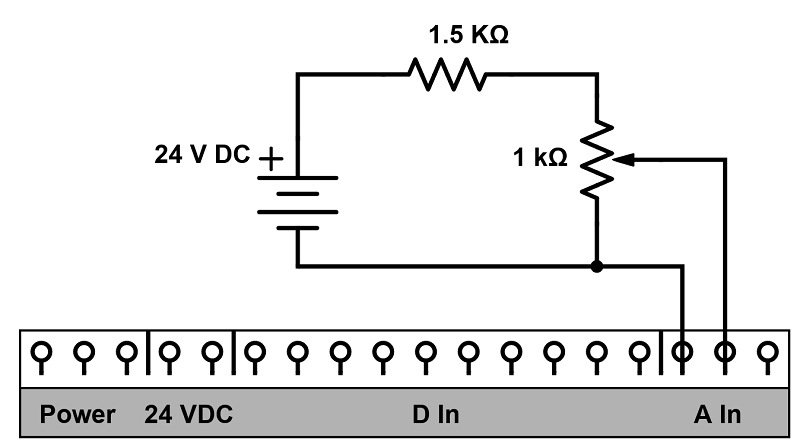
Figure 2. Visual representation of the top of an S7-1200 with the analog terminals on the upper right (note: not all digital terminals may be shown).
A keen mathemetician may notice that this voltage divider will not precisely reach 10 V, but as luck would have it, my old potentiometer exceeds 1 kΩ, so the net result is a tutorial that must address calibration in order to achieve a correct output.
Analog Input Programming
Following the previous tutorial, a few tags were created to connect some discrete I/O points.
This time, we need to create tags for the analog points, but they are no longer discrete tags. The size of the variables created for analog inputs is 16 bits; most of the time, these would be called integers (INTs) with a single address. However, in the TIA Portal, these are constructed as two bytes, consuming two consecutive byte memory addresses. This is called a ‘word’, so we must create a Word data type.
Since the analog inputs are built into the hardware, the memory allocation for both inputs is also baked right in, but they are not simply the first two addresses—it’s a bit more complex.
The first analog input begins at memory address IW64. Since it takes up two addresses, the second analog input begins at address IW66.
What Is the Memory Address for the Analog Inputs in an S7-1200?
In your project, double-click on ‘Device configuration.’

Figure 3. Device configuration.
If the PLC is selected, there will be a ‘Properties’ window open at the bottom of the screen. Select the I/O addresses under the Analog inputs, which will display the start and end addresses for both inputs.
As you can see below, the first input consumes addresses 64 and 65, and then the second one consumes 66 and 67.

Figure 4. S7-1200 analog input memory addresses.
In this way, both analog input tags can be created using the data type: Word and the starting addresses, as shown below.

Figure 5. Analog input tags.
Back in the Main program block, a ladder rung can now be designed to convert or store the analog value to perform any desired task.
When the analog-to-digital converter (ADC) provides an output to the PLC, it is converted to a standard value range of 0-27648, meaning that 0 V display a ‘0’ for Analog_In_1, and exactly 10 V display a ‘27648’.
At this time, you could connect and navigate to a watch table to see the value. The tag's value can be monitored in the Default tag table, but it is a hexadecimal value by default. This 16-bit word will show a 4-character hex number. Easy to convert to binary…but not as easy to imagine as a decimal value. In the watch table, add the input tag, select the DEC display format, and ensure you are online and monitoring.
Using the NORM_X Command in TIA Portal
Converting 10 V into a value of 27648 provides a lot of precision but isn't a terribly useful value. Instead, we could change that value into a computed output value or display it on an HMI to show the true output of the sensor (in reality, it may be temperature or pressure).
This scaling process consists of two steps. TIA portal contains a NORM_X and a SCALE_X command, where ‘normalize’ first reduces a range of integer values into a single decimal value between 0 and 1. This requires creating a Real tag in the tag list to store this normalized value.
I called this tag simply ‘Norm_Val’ with a Real address of MD20 (memory, 32-bit double integer size for the IEEE float construct, and location 20 was sure not to interfere with any previously created tags. You may choose to use something different).

Figure 6. Real value to store normalized analog input.
Finally, with all the building blocks in place, we can create a ladder network to examine the anticipated range of the incoming analog value and convert this into the equivalent 0-1 decimal value.
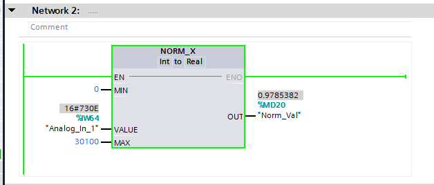
Figure 7. NORM_X serves to normalize a value into a 0-1 decimal value.
Several steps are completed in this block.
-
The input and output data types must be determined. In this case, the input is an Int (16 bits, although I do not know why ‘Word’ is not presented as an option to match the data type), and the output is a Real.
-
The MIN anticipated value is 0
-
The MAX anticipated value, as determined by examining the Watch table as I turned the potentiometer, actually exceeded 10 V and was right about 30100.
-
The VALUE is the address of the analog input.
-
The OUT destination is that Real tag we created. If we use an integer value in this command output, it will be truncated and always appear as 0.
Now, you can turn the potentiometer and fine-tune your own values. Perhaps it does not go down to 0 V exactly, and maybe you used a different resistor, and it does not reach 30000 as mine did. The OUT value should swing from 0 to 0.9999 or as close to 1.0 as possible through the entire input value range.
In reality, the input signal will probably not transition from 0 to 10 V. It will likely be a pressure or temperature sensor, which might be capable of a large value range, but only a fractional change will be seen for your process. This NORM_X command allows you to identify the actual MIN and MAX expected values, providing much greater precision to the OUT value of the command.
Produce Meaningful Values Using Real Data Type
The SCALE_X command will be explained in its entirety in the following article to illustrate its use in providing an analog output. However, the construction is similar to the NORM_X, and both must be used together in most cases since the NORM will reduce the value to a known range, then the second will increase it to a second known larger range. Some IDEs combine both processes into a single linear equation format, with both input and output min and max values provided, but this process splits it into two simple steps.
Analog Inputs in TIA Portal
The practical use of analog values is more complex than discrete signals, but they must be understood due to the common occurrence of analog signals in the real world. This guide can help make the most of your Siemens TIA Portal programming experience, regardless of whether your analog signals come from the built-in terminals or one of the many add-on modules or signal boards available for the platform.