Facebook
 Google
 GitHub
 Linkedin
Understanding Inputs and Outputs for Servo Drives
Servo drives interact with hardware axes, but there are many ways to configure the motion. I/O signals allow connections of sensors and switches for functions like homing and setting travel limits.
If you’ve never worked with servo motor drives, it’s quite different from asynchronous 3-phase motors driven by VFDs. The main difference is in the feedback. VFDs operate in an open-loop system, where any feedback control is connected to an external controller. Servos, on he other hand, have an integrated encoder, so you must determine motion parameters for the entire system before allowing it to run.
Previous articles have discussed some example setups of a hardware axis and inputting the specs into the drive software (like this tutorial), but it’s time to take a deeper look into the types of I/O signals that need to be understood for various types of motion.
In particular, there are three types of input signals to be aware of in servo systems: limit signals, homing input signals, and general input signals.
Limit Switches
We need to be careful with terminology in this first case. A limit switch is a category of hardware switch that is activated by force on a lever or roller. It can be used in all kinds of object detection scenarios.
However, in motor control, there are many types of switches that detect the presence of a traveling object when it reaches the end of its path. These are also called ‘limit’ switches. For most axes, there would be a limit switch installed at both ends of the travel stroke: a positive limit and a negative limit.
These limit switches for motion axes are not always mechanical. There are many non-contact switches that use optical or magnetic properties to detect travel without encountering any mechanical resistance.
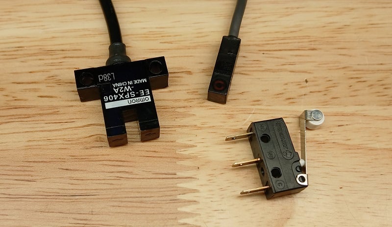
Figure 1. A few examples of hardware limit switches, CW from top left: optical slot sensor, magnetic reed switch, micro limit switch.
Software Limits
Do you need limit switches? No. Often you don’t.
Most servo drives can handle software limits, where the encoder tracks the motion, and the controller will not allow it to travel past a certain threshold.
Homing Switch
The next kind of digital input is called a ‘homing’ input. Usually, there is just one homing switch, because this operation is performed as a single-directional motion at startup, or in response to a deliberate command. When you remove power to the axis, it erases the current position (unless there is a battery backup, like in robot servos). Homing essentially allows the controller to re-establish a known starting point for all future motion.
Fixed End Home Position
There are many kinds of homing used for motion control. The most common (and easiest to understand) is when the platform moves slowly in one direction until it hits the homing switch, and that immediately becomes the ‘zero’ position. In a slight variation, it may hit the homing switch, then reverse and move very, very slowly back again until the sensor de-energizes. As you can imagine, a tactile limit switch with a lever arm may slowly wear over time, and we'd find that the home position has shifted by mere fractions of a mm. This is why non-contact switches may be more appealing.
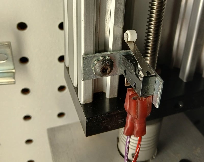
Figure 2. This homing switch is fixed near the motor end of the axis.
Intermediate Home Position
Another homing method allows the motion component to pick one direction and move until it reaches a limit switch, then reverse directions and proceed until it reaches the homing switch. This assumes that the homing switch is located at an intermediate position, and on startup, it is unknown which direction the platform must travel to reach it. Once again, a non-contact switch may be preferred, since the motion carriage will travel past the homing switch every time it moves from one end to the other.
Software Homing
There are software homing methods that ignore the application of a hardware switch entirely. If the carriage will remain at a known, fixed position every time the machine powers down, then this position may be automatically assumed to be the ‘zero’ position at each startup. However, be warned; if the motion carriage is not at a consistent position, the zero position will be assigned to that random spot on startup. Then, when you command the axis to drive to a position of 400 mm, it may try to overrun the end of the axis.
Safe Torque Off (STO) Inputs
From a safety perspective, we need to have a method of protecting the equipment and users in emergency situations. The dual inputs are called safe torque off, or STO1 and STO2. These must receive a voltage signal or the drive will be commanded to a halt. Most often, this would be connected to an E-stop circuit or a safety relay with dual normally-closed contacts.
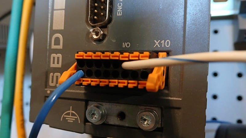
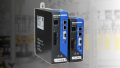
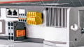
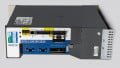
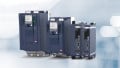
Figure 3. The I/O header from a CMZ SBD servo drive unit.
General Purpose Inputs
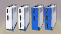
We have covered most of the primary tasks of an input signal into a servo drive. However, some drive units run more than just the motor. Consider the example of an SBD drive from CMZ Sistemi Elettronici, which includes not just the servo capability, but also an embedded PLC that executes structured test code.
As with any PLC, there must be a way to receive process inputs from sensors and user-operated buttons. These general-purpose I/O (often abbreviated GPIO) signals can be used for any kind of signal, much like with any other PL; they do not have a pre-defined purpose. Not all servo drives have GPIO headers.
Servo Motion
Certainly, servo controls are much harder to configure than VFDs. But, at the same time, there are many commissioning tools to ease the time commitment, so the barrier is slowly being removed. For those who have not yet experimented with servo systems, it’s never too late to learn!
Images used courtesy of the author.
Interested in servo motion? Here are some more articles:
Motion Control: It’s More Than Just “Point A to Point B”
Tutorial: Single-Axis Motion Control with CMZ Drive
Motion Control Tutorial: Setting up a Linear Axis