Facebook
 Google
 GitHub
 Linkedin
CNC Hardware and PLC Hardware Signal Differences
Learn all about the differences between PLC and CNC hardware, and be informed in making the right decision. Although different, it is possible to interchange them, but challenges exist because of the hardware and devices being controlled.
Almost every modern industrial control system is driven by a digital processor. Two of the most common examples of these systems are CNC machines and entire processes driven by PLCs. Even though the physical computer chips inside the controllers may be closely related, there are differences between the two controllers. It can be possible to interchange them, but challenges exist because of the hardware and devices being controlled.

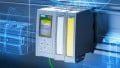
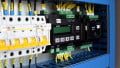
Figure 1. CNC machining requires specific hardware to accurately perform its job.
In previous articles, we have discussed the differences between the programs and codes that operate control system processes versus the codes that run CNC machines to create parts using machining processes. In some cases, it is possible to use a PLC to drive a CNC machine, since at the very fundamental level they both use digital controllers to drive output devices. However, there are usually some extra challenges that might make such a substitution very difficult. The software differences are the first challenge.
This article discusses a variety of hardware differences between CNCs and PLCs. The purpose is not to assert that it is impossible to convert between controllers, but rather to explain the various elements that must be addressed in order for the machine to operate properly.
In contrast to the software differences, which were quite extreme, the input and output hardware connections are actually quite similar between the two kinds of controllers.
Input Signals
Input signals are one case where the purpose of the PLC may actually lend itself quite well to signals produced by a CNC machine.
At a minimum, the CNC frame usually includes some sort of micro limit switch or contactless limit switch. These digital signals not only provide a sense of location to prevent damaging over-travel of an axis, but they are also used to ‘home’ a machine at the start of a program to provide a sense of location in reference to the workpiece. Since these are digital signals, they are an ideal input device for a PLC.
Some CNC machines will also include encoders for location feedback during the machining operation. They might either be a rotary encoder on the axis motor, or linear strip encoders along the length of the axis. In either case, encoders are a common input to a PLC, making it another fairly easy hardware integration.
Some advanced CNC applications may include extra input signals. These might include an electrical edge finder stylus for locating the edges of parts or indices for selecting from a variety of different end tool types. These may not be present on all machines, but if they provide digital input signals, they might be well-suited for a PLC input terminal.
Output Signals
The category of outputs leads to a few more difficult challenges. Most CNC systems have multiple axes (2-3 or even more) driven by stepper or servo motors. Therefore, the control systems driving them must be able to communicate directly with those motors. PLCs do interface with motors. However, this is more likely to be an external three-phase variable frequency drive (VFD) or a servo controller.
If using a PLC to drive motion axes, it will probably be necessary to provide a sufficient servo or stepper driver board. Those driver boards will require signals that switch at a high frequency with variable duty cycles. The PLC must be capable of providing these signals, usually called pulse width modulation (PWM) with constant frequencies, or ‘pulse trains’ with variable frequencies. If the PLC has relay outputs, it will most certainly not be able to drive a motion axis.
The other output signal from the controller is the signal that drives the tool head itself. If this is a rotating spindle, it may be a three-phase motor using a VFD. This is perfect for a PLC. For other tool heads such as a laser, plasma cutter, or other non-rotational tools, the signal may need to be an additional PWM to provide variable output power.
Summary
Using a PLC in place of a CNC controller requires forethought in both the area of software and programming as well as the hardware connections. The hardware is usually the simplest challenge. Inputs provide positional information which are digital signals and encoders — perfect for a PLC. The output devices must simply be capable of providing the proper signals for motion axes — usually PWM or pulse train signals.
Choosing to replace a CNC control board with a PLC may not be an easy task. It is almost always possible, but providing the proper input commands to drive the motion axes is the most difficult part of the process unless the CNC program to be completed is simple and consistent.
PLCs are designed for repetitive tasks that are based on real-world events and signals. CNC controllers are meant to convert virtual, digital tool paths into real-world motions with little to no outside signals during the program execution.
As long as both software and hardware challenges are addressed, the result may be a very effective PLC machine control system.
Related Content