Facebook
 Google
 GitHub
 Linkedin
Introducing the Split-Range Time-Proportioning Instruction
A useful but often overlooked instruction included in Allen-Bradley ControlLogix and CompactLogix PLCs for heating and cooling.
The instruction set of the Allen-Bradley ControlLogix and CompactLogix controllers is quite extensive. So it is no surprise that there are many instructions that the average user may never use or even be aware of. The Split-Range Time-Proportioning instruction, abbreviated SRTP, is no exception.
I have been using Allen-Bradley ControlLogix products since their release over 20 years ago, and I just stumbled upon this instruction a few years ago, hidden within the process control instruction group of the ControlLogix and CompactLogix instruction set.
The SRTP instruction is only available as a function block or structured text instruction, and unfortunately, is not available in ladder logic form.
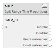
Figure 1. The Function Block depiction of the SRTP instruction.
How SRTP Instruction Works
The SRTP uses an analog signal as an input, typically from a PID loop, and converts it to a pulsed digital signal with a duty cycle relative to the analog input with minimum and maximum scaling configuration settings applied. The instruction also can split the digital signal into two parts, each responding only to a given range of the input signal (i.e., 0–50% can be configured to control the first digital output while 51–100% can be configured to actuate the second digital output).
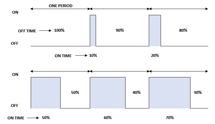
Figure 2. Time proportional output example, sometimes referred to as pulse width modulation (PWM).
The digital outputs are labeled “HeatOut” and “CoolOut,” as this instruction is often used to control a heating/cooling process. When only heating or cooling is desired, but not both, a user can configure the entire input range for either heating or cooling, and ignore the other unwanted output. The output resembles a commonly known signal referred to as pulse width modulation (PWM).
Uses for SRTP Instruction
The most typical use for the SRTP instruction is to convert an analog output from a PID controller to a pulsed output for heating and/or cooling applications. Since the PID instruction within ControlLogix and CompactLogix has an analog output, a conversion is needed to use the PID instruction with a digital output.
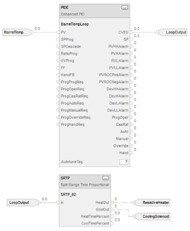
Figure 3. The SRTP instruction is shown used with a PIDE instruction.
When the pulsed output is used in conjunction with a solid-state relay, the duty cycle of an electric heater attached to the solid-state relay can be controlled, thus controlling the amount of heat to a process. When cooling is needed, the cooling output is typically connected to a solenoid that would control a liquid coolant or water flow to a process.
SRTP Instruction Settings
There are nine basic settings used to make the instruction operational. Four are associated with the heating output, four are associated with cooling output, and one is common to both heating and cooling.
The four heating settings are the following.
- Minimum heat input
- Maximum heat input
- Minimum heat time
- Maximum heat time
The minimum heat input is the percentage of the input signal representing the minimum amount of heating output pulse. The maximum heat input is the percentage of the input signal representing the maximum amount of heating output pulse. When both heating and cooling are used in a split system, typical settings for the minimum and maximum heat input are 50% and 100%, respectively.
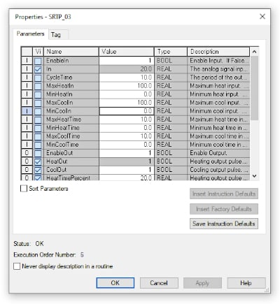
Figure 4. Some basic settings are shown for the SRTP instruction.
The minimum and maximum heat times are boundary limits for the heating output pulse. The minimum heat time is the minimum time in seconds that the heating output pulse will be on, regardless of the calculated pulse time. Similarly, the maximum heat time is the maximum time in seconds that the heating output pulse will be on, regardless of the calculated value.
The four cooling settings are the following.
- Minimum cool input
- Maximum cool input
- Minimum cool time
- Maximum cool time
The cooling settings are very similar to the heating settings, with the only difference being they affect the cooling output instead of the heating output. Otherwise, the definitions and functions are identical.
The one common setting between the two modes is the cycle time, which can be thought of as the period of the output pulses. The cycle time sets the period (in seconds) of the heating and cooling output pulses.
Using the SRTP instruction can save time and can simplify the logic when an analog signal needs to be converted to a PWM digital output. The instruction has fairly straightforward configuration options and, once used, is easy to understand.
Implementing the equivalent or a substitute logic solution would likely look cumbersome and more difficult to understand. Hopefully, this article will make you aware of the instruction and inspire you to try it in your next application.