 Facebook
 Google
 GitHub
 Linkedin
Mechanisms of Linear Sensing and Linear Encoding
Linear sensors use electrical means to determine their position. Common linear position sensors are resistive, inductive, capacitive, and many rely on a property called magnetostriction.
Any automation that requires motion must be tracked. At any point in time, the automation system must track where an object is located currently, as well as where it is headed. This allows the system to properly position objects as well as maintain safe distances between machines and people.
The position of the object is measured with the linear sensor or linear encoder and compared to the automation program to see where it should be located. If it is not exactly on the target location, the automation system sends a control signal to an actuator that will continue to move the actuator.

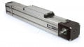
Figure 1. Position sensors are commonly used on linear axes when precise position and speed are required. Image used courtesy of Canva
These linear sensors act not only to measure position alone, but also as velocity sensors in many cases. The linear actuator is sampled at a regular interval. Its velocity is the change in position over the time between most recent samples. This number can be positive or negative, as the linear sensor measures along one dimension. In the same manner, further calculations of acceleration and other properties can be calculated.
Linear Sensing Methods
By far, electrical means of detecting position are the most common in the automation field. Common linear position sensors are resistance (and voltage drop), inductive, capacitive, and many rely on a property called magnetostriction.
Linear sensors use electrical means to determine their position. They are most commonly used to find absolute position, where the value recorded is on an absolute scale and represents and absolute distance from the starting point of the sensor.
Resistive
A potentiometer can be used to determine position. The most simple form is to have the measurement end of the sensor mounted to a wiper that travels along a linear potentiometer. As the shaft extends, the wiper moves farther away, increasing the resistance and the voltage drop across its length. This type of sensor will either include a calibration chart or can be calibrated using a linear regression model, comparing resistance (or voltage) to a few set, known lengths.
While resistive sensors are the simplest and often cheapest, they rely on a wiper to drag across the surface of a potentiometer. The wiper is a source of drag, which can act to limit motion and the friction causes slow accuracy drift and eventual component failure.

Figure 2. Resistive linear position sensors (linear potentiometers) are simple enough to be integrated into many applications, including this home-built saw measurement application.
Inductive
Inductive linear position sensors rely on changing magnetic fields to determine position. There are several configurations, the first of which uses an injected current into one coil, and detecting the field with another coil. At the end of the sensor is a magnetic material so that as it passes between the two coils, the field changes. Another configuration relies on eddy currents that change as the end of the sensor moves.
For sensitive electronics nearby, inductive sensors may not be the best choice, as they generate a potentially interfering magnetic field around the coil. However, inductive sensors have very low friction, meaning they can be used to take very precise measurements with little wear over time.
Capacitive
In a parallel plate capacitor, the capacitance is a function of the dielectric constant of the material between the plates, the separation between the two parallel plates, as well as the overlapping area of the two plates. In a capacitive linear position sensor, the motion causes one of the parallel plates in a capacitor to move. This shift changes the capacitance. Depending on the configuration, the movement will either press the plates together, or will slide them past one another.
Capacitive sensors can be low friction, particularly if they use air as a dielectric. However, the dielectric properties can change over time, so attention to calibration is necessary. This method can be great for close-up measurements with attention to precision rather than length of measurement stroke.
Magnetostrictive
Linear sensors for actuators often rely on a current pulsed into a conductor passed through the center of the actuator. A magnet placed on the piston end interacts with the current and causes a change in the physical properties of the material, based on its position.
This is a very precise, long-life sensor because there is no physical interaction between signal and magnet. Magnetostrictive linear transducers are very common in long-stroke hydraulic motion control applications.

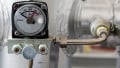
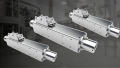
Figure 3. Magnetostrictive sensors are common for industrial linear cylinder applications. Image used courtesy of Temposonics
Linear Encoders
A subset of linear sensing is the linear encoder. Linear encoders “count” the distance they have traveled. They can be used to determine absolute or relative position based on the number of counts.
A linear encoder “counts” some quantity that is linked to distance. While encoders take advantage of the same physical phenomena as other linear sensors, there are a few other methods, such as optical sensing.
Optical
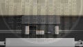
With an optical linear encoder, a simple electronic eye counts the number of pulses as it moves along a striped tape. The striped tape is alternated white and black, and the sensor typically counts the black lines. Because the stripes are at regular intervals, the number of counts corresponds to a linear distance. Depending on the arrangement, light is either reflected off the tape and detected by the sensor or transmitted through the tape, where the dark stripes block the light from the sensor.

Figure 4. Optical linear encoder with a series of fine dark marks. In the close-up view, the teeth on the edge of a dime are shown for scale. Image courtesy of Control.com engineer’s wife’s microscope.
Optical linear encoders are especially accurate, provided they have a mechanism to ensure that the tape does not become worn, damaged, smeared, or obstructed with debris. Depending on the light source, one should periodically check the tape to ensure that it is not deteriorating. With LED light sources, this is less of an issue than when it was when incandescent bulbs were used for lighting.
Magnetic
The same principle can be applied to magnetic linear encoders. The tape is instead lined with magnetic materials of different orientations at regular intervals. A magnetic sensor detects the changes in the magnetic field and counts the number of pulses that pass under the sensor.

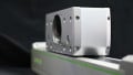
Figure 5. Magnetic structures in a repeating pattern are used in a magnetic linear encoder. Image used courtesy of Wikipedia.
The Future of Linear Sensing
Linear sensors are here to stay. As long as there is motion, there is a need for sensing position and velocity. In the future, the resolution will only improve on these devices, making it possible to detect smaller position changes, within certain limitations. As control algorithms improve, predictive motion will also improve, taking full advantage of the linear sensor’s ever-increasing fine resolution.


We note you refer to Laser Measurement in the first link of ‘Related Content’.
However it is worth mentioning ‘Draw Wire Position Sensing’. This is basically a multiturn potentiometer [possibly geared down] pulling a draw wire out of the housing, not disssimilar to pulling the metal tape out of a measuring tape. The difference is the draw wire pulls back in automatically.
Obviously used where the effort to pull is negligable compared to the equipment size; it can be used in harsh and in particular water environments where measured device goes under, such as sluice gates.
An obvious disadvantage is that foreign material can enter the transducer with the drawire, although can be negated by orientation. Only once have I seen mould growth enter, on the wire itself which had been immersed in dam water for several months.
https://www.micro-epsilon.co.uk/displacement-position-sensors/draw-wire-sensor/?
https://www.seatools.com/subsea-components/wire-length-measurement-sensor/