 Facebook
 Google
 GitHub
 Linkedin
Electricity and Electronics
DC Circuit Calculations
37 questions
-
Question 1 of 37
Calculate the amount of voltage between points A and B in this circuit. You must sketch polarity marks (+ , -) on the schematic diagram to show the polarity of $V_{AB}$, as well as show all of your mathematical work!
 Reveal answer
Key Application for this Solution: Ohm’s Law
$V_{AB}$ = 9.198 volts, A being the higher voltage point than B.
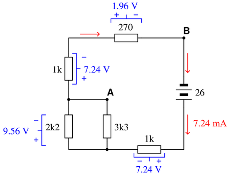
The voltage between points A and B is the supply voltage (26 volts) minus the voltage drops across the 1k and parallel subnetwork resistors. Alternatively, one could calculate $V_{AB}$ by adding the voltage drops of the 1k and 270 ohm resistors.
The latter solution makes it easiest to see the polarity of $V_{AB}$: noting how the voltage drops across the 1k and 270 ohm resistors are additive, we see point A being the most positive and point B being the most negative.
The solution is derived by combining all resistors into one equivalent value and applying Ohm’s Law to determine the circuit current and, subsequently, the voltage drop across each resistor.
Assuming resistor numbering with the 270 $\Omega$ resistor as the 5th and final resistor:
$$R_{total}=R_1+1/(1/R_2+1/R_3)+R_4+R_5$$
$$R_{total}=3.59~k \Omega$$
$$I_{total}={26~V \over 3.59~k \Omega}$$
$$I_{total}=7.24~mA$$
$$V_{R_1}=7.24~mA \cdot 1~k \Omega$$
$$V_{R_1}=7.24~V$$
$$V_{R_{2,3}}=7.24~mA \cdot 1.32~k \Omega$$
$$V_{R_{2,3}}=9.56~V$$
$$V_{R_4}=7.24~mA \cdot 1~k \Omega$$
$$V_{R_4}=7.24~V$$
$$V_{R_5}=7.24~mA \cdot 270~ \Omega$$
$$V_{R_5}=1.96~V$$
-
Question 2 of 37
Calculate the resistance between points A and B ($R_{AB}$) for the following resistor networks:
 Reveal answer
Key Application for this Solution: Resistor Network Equivalents
Figure 1:
Two equal parallel paths, each consisting of two series 500 Ω resistors.
Two 1000 Ω resistors in parallel equals 500 Ω.
$R_{AB}$ = 500 Ω
Figure 2:
One 1000 Ω resistor in parallel with three equal series resistors (3000 Ω total).
1000 Ω in parallel with 3000 Ω equals 750 Ω.
$R_{AB}$ = 750 Ω
Figure 3:
This is a series of two parallel networks. The first network has a 2000 Ω and a 5000 Ω in parallel (1429 Ω). The second network has a 100 Ω and a 470 Ω in parallel (82 Ω).
$R_{AB}$ = 1429 Ω + 82 Ω.
$R_{AB}$ = 1.511 kΩ
Figure 4:
A bit of a ‘trick’ problem. After the current passes through the 940 Ω resistor, it may pass unresisted to point B. Therefore, the 470 Ω and 250 Ω resistors are not factored into the equation.
In other words, those two latter resistors have been ‘shorted’ out of the equation, and all resistance in that path is now in parallel with a ‘nearly 0 Ω resistor’. According to the parallel circuit equation, when one parallel resistor is nearly zero, the equivalent network resistance is also nearly zero.
$R_{AB}$ = 940 Ω
Figure 5:
Three parallel networks, from left to right, include one 2.2 kΩ, a second 2.2 kΩ, and then a series consisting of two 2.2 kΩ, for a 4.4 kΩ equivalent.
A parallel network of 2.2 kΩ, 2.2 kΩ, and 4.4 kΩ equals 880 Ω.
$R_{AB}$ = 880 Ω
Figure 6:
This circuit can be difficult to visualize without mentally or physically redrawing the resistor arrangement.
Between A and B lie a 100 Ω resistor, this is plain. But in addition, there lies a second path with a 220 Ω resistor followed by parallel branches of 470 Ω and 330 Ω, either of which presents possible paths to B.
The equivalent resistance, then, is found by:
470 Ω and 330 Ω in parallel = 194 Ω
This is in series with (added to) 220 Ω to = 414 Ω
This 414 Ω is in parallel with 100 Ω to = 80.5 Ω
$R_{AB}$ = 80.5 Ω
Notes:Discuss with your students how they approached each of these problems, and let the entire class participate in the reasoning process. The point of this question, like most of the questions in the Socratic Electronics project, is not merely to obtain the correct answers, but to stimulate understanding of {\it how} to solve problems such as these.
-
Question 3 of 37
Use Kirchhoff’s Voltage Law to calculate the magnitude and polarity of the voltage across resistors $R_2$ and $R_4$ in this resistor network:
 Reveal answer
Key Application for this Solution: Kirchhoff’s Voltage Law (KVL)
“The Sum of All Voltage Drops in a Closed Loop Equal 0”
This can be rephrased to state that all increases in voltage must be equal to drops in voltage in any closed loop.
For the loop on the left, this is simple:
$$V_{source} = V_{R1}+V_{R3}+V_{R2}$$
$$17~V=10~V+4~V+V_{R2}$$
$$V_{R2} = 3~V$$
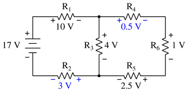
But for the loop on the right, with no source voltage, the polarity of each resistor must be carefully observed, and the true purpose of Kirchhoff’s Law is revealed.
If a loop is drawn in a clockwise manner around the right-side closed loop, $R_4$, $R_6$, and $R_5$ are a positive drop in voltage (going from + to -), but $R_3$ is actually an increase, or a negative drop (- to +).
Therefore, we return to Kirchhoff’s Law in its true form, and add all of these drops to equal 0:
$$V_{R4}+V_{R6}+V_{R5}-V_{R3}=0$$
$$V_{R4}+1+2.5-4=0$$
$$V_{R4}-0.5=0$$
$$V_{R4}=0.5$$
Notes:In your discussion, be sure to explore more than one “loop” when using KVL. Not only does this demonstrate the arbitrary nature of your loop choice, but it also serves as a double-check for your work!
It is not necessary to know anything about series-parallel or even parallel circuits in order to solve for R_2’s or R_4’s voltage—all one needs to know is how to use Kirchhoff’s Voltage Law.


So good
circuits analysis and theorems. So good!!