Facebook
 Google
 GitHub
 Linkedin
Electricity and Electronics
Fault Analysis of Simple Circuits
-
Question 1
Suppose a voltmeter registers 0 volts between test points C and F, but measures 24 volts between those same test points when the connection between B and C is broken:

Identify the likelihood of each specified fault for this circuit. Consider each fault one at a time (i.e. no coincidental faults), determining whether or not each fault could independently account for all measurements and symptoms in this circuit.
$$\begin{array} {|l|l|} \hline Fault & Possible & Impossible \\ \hline R_1~Failed~open & & \\ \hline R_2~Failed~open & & \\ \hline Q_1~Failed~open & & \\ \hline R_1~Failed~shorted & & \\ \hline R_2~Failed~shorted & & \\ \hline Q_1~Failed~shorted & & \\ \hline Voltage~source~dead & & \\ \hline \end{array}$$
Reveal answer$$\begin{array} {|l|l|} \hline Fault & Possible & Impossible \\ \hline R_1~Failed~open & & \surd \\ \hline R_2~Failed~open & & \surd \\ \hline Q_1~Failed~open & & \surd \\ \hline R_1~Failed~shorted & & \surd \\ \hline R_2~Failed~shorted & & \surd \\ \hline Q_1~Failed~shorted & \surd & \\ \hline Voltage~source~dead & & \surd \\ \hline \end{array}$$
-
Question 2
Suppose this electric-driven air compressor cycles between 60 PSI and 105 PSI when the switch is in the “Auto” position, and cycles between 102 PSI and 105 PSI when in the “Hand” position:
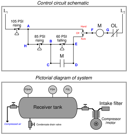
Identify the likelihood of each specified fault for this circuit. Consider each fault one at a time (i.e. no coincidental faults), determining whether or not each fault could independently account for all measurements and symptoms in this circuit.
$$\begin{array} {|l|l|} \hline Fault & Possible & Impossible \\ \hline PSHH~Failed~open & & \\ \hline PSH~Failed~open & & \\ \hline PSL~Failed~open & & \\ \hline Aux~“M”~contact~failed~open & & \\ \hline PSHH~Failed~shorted & & \\ \hline PSH~Failed~shorted & & \\ \hline PSL~Failed~shorted & & \\ \hline Aux~“M”~contact~failed~shorted & & \\ \hline \end{array}$$
Reveal answer$$\begin{array} {|l|l|} \hline Fault & Possible & Impossible \\ \hline PSHH~Failed~open & & \surd \\ \hline PSH~Failed~open & & \surd \\ \hline PSL~Failed~open & & \surd \\ \hline Aux~“M”~contact~failed~open & & \surd \\ \hline PSHH~Failed~shorted & & \surd \\ \hline PSH~Failed~shorted & \surd & \\ \hline PSL~Failed~shorted & & \surd \\ \hline Aux~“M”~contact~failed~shorted & & \surd \\ \hline \end{array}$$
Notes:This question is a good candidate for a “Virtual Troubleshooting” exercise. Presenting the diagram to students, you first imagine in your own mind a particular fault in the system. Then, you present one or more symptoms of that fault (something noticeable by an operator or other user of the system). Students then propose various diagnostic tests to perform on this system to identify the nature and location of the fault, as though they were technicians trying to troubleshoot the problem. Your job is to tell them what the result(s) would be for each of the proposed diagnostic tests, documenting those results where all the students can see.
During and after the exercise, it is good to ask students follow-up questions such as:
{\bullet} What does the result of the last Diagnostic~test tell you about the fault?
{\bullet} Suppose the results of the last Diagnostic~test were different. What then would that result tell you about the fault?
{\bullet} Is the last Diagnostic~test the best one we could do?
{\bullet} What would be the ideal order of tests, to diagnose the problem in as few steps as possible? -
Question 3
Suppose this electric-driven air compressor refuses to start when the switch is in the “Auto” position, but starts up immediately when the switch is placed in the “Hand” position. The first test performed by a technician is to measure AC voltage between test points A and F with the switch in the “Auto” position. There, the meter registers 117 volts AC. You are then called in to help:

Identify the likelihood of each specified fault for this circuit. Consider each fault one at a time (i.e. no coincidental faults), determining whether or not each fault could independently account for all measurements and symptoms in this circuit.
$$\begin{array} {|l|l|} \hline Fault & Possible & Impossible \\ \hline PSHH~Failed~open & & \\ \hline PSH~Failed~open & & \\ \hline PSL~Failed~open & & \\ \hline “Hand”~switch~position~failed~open & & \\ \hline “Auto”~switch~position~failed~open & & \\ \hline OL~contact~failed~open & & \\ \hline Aux~“M”~contact~failed & & \\ \hline Contactor~“M”~coil~failed~open & & \\ \hline \end{array}$$
Reveal answer$$\begin{array} {|l|l|} \hline Fault & Possible & Impossible \\ \hline PSHH~Failed~open & & \surd \\ \hline PSH~Failed~open & \surd & \\ \hline PSL~Failed~open & \surd & \\ \hline “Hand”~switch~position~failed~open & & \surd \\ \hline “Auto”~switch~position~failed~open & \surd & \\ \hline OL~contact~failed~open & & \surd \\ \hline Aux~“M”~contact~failed & & \surd \\ \hline Contactor~“M”~coil~failed~open & & \surd \\ \hline \end{array}$$
Notes:This question is a good candidate for a “Virtual Troubleshooting” exercise. Presenting the diagram to students, you first imagine in your own mind a particular fault in the system. Then, you present one or more symptoms of that fault (something noticeable by an operator or other user of the system). Students then propose various diagnostic tests to perform on this system to identify the nature and location of the fault, as though they were technicians trying to troubleshoot the problem. Your job is to tell them what the result(s) would be for each of the proposed diagnostic tests, documenting those results where all the students can see.
During and after the exercise, it is good to ask students follow-up questions such as:
{\bullet} What does the result of the last Diagnostic~test tell you about the fault?
{\bullet} Suppose the results of the last Diagnostic~test were different. What then would that result tell you about the fault?
{\bullet} Is the last Diagnostic~test the best one we could do?
{\bullet} What would be the ideal order of tests, to diagnose the problem in as few steps as possible? -
Question 4
An Automation Direct model C0-08TD2 “sourcing” DC output PLC module uses the following internal circuitry to switch DC power to a load:

Suppose the microprocessor is sending a “high” (1) signal to the switching circuitry, but the DC load refuses to energize. Using your DC voltmeter, you measure 24.7 volts DC between the “+V” and “Com” terminals, and 0 volts DC between the “Out” and “Com” terminals.
Identify the likelihood of each specified fault for this circuit. Consider each fault one at a time (i.e. no coincidental faults), determining whether or not each fault could independently account for all measurements and symptoms in this circuit.
$$\begin{array} {|l|l|} \hline Fault & Possible & Impossible \\ \hline Diode~D_1~Failed~shorted & & \\ \hline Diode~D_2~Failed~open & & \\ \hline Diode~D_3~Failed~open & & \\ \hline Diode~D_4~Failed~open & & \\ \hline Transistor~Q_1~Failed~open & & \\ \hline Transistor~Q_2~Failed~open & & \\ \hline Transistor~Q_3~Failed~shorted & & \\ \hline Capacitor~C_1~Failed~open & & \\ \hline Resistor~R_1~Failed~shorted & & \\ \hline Resistor~R_2~Failed~shorted & & \\ \hline Resistor~R_3~Failed~open & & \\ \hline Resistor~R_4~Failed~open & & \\ \hline Resistor~R_5~Failed~shorted & & \\ \hline Resistor~R_6~Failed~open & & \\ \hline \end{array}$$
Reveal answer$$\begin{array} {|l|l|} \hline Fault & Possible & Impossible \\ \hline Diode~D_1~Failed~shorted & & \surd \\ \hline Diode~D_2~Failed~open & \surd & \\ \hline Diode~D_3~Failed~open & \surd & \\ \hline Diode~D_4~Failed~open & & \surd \\ \hline Transistor~Q_1~Failed~open & \surd & \\ \hline Transistor~Q_2~Failed~open & \surd & \\ \hline Transistor~Q_3~Failed~shorted & & \surd \\ \hline Capacitor~C_1~Failed~open & & \surd \\ \hline Resistor~R_1~Failed~shorted & & \surd \\ \hline Resistor~R_2~Failed~shorted & & \surd \\ \hline Resistor~R_3~Failed~open & \surd & \\ \hline Resistor~R_4~Failed~open & & \surd \\ \hline Resistor~R_5~Failed~shorted & \surd & \\ \hline Resistor~R_6~Failed~open & \surd & \\ \hline \end{array}$$
-
Question 5
An Automation Direct model C0-08TD1 “sinking” DC output PLC module uses the following internal circuitry to switch DC power to a load:

Suppose the microprocessor is sending a “high” (1) signal to the switching circuitry, but the DC load refuses to energize. Using your DC voltmeter, you measure 24.7 volts DC between the “+V” and “Com” terminals, and 23.2 volts DC between the “Out” and “Com” terminals.
Identify the likelihood of each specified fault for this circuit. Consider each fault one at a time (i.e. no coincidental faults), determining whether or not each fault could independently account for all measurements and symptoms in this circuit.
$$\begin{array} {|l|l|} \hline Fault & Possible & Impossible \\ \hline Diode~D_1~Failed~open & & \\ \hline Diode~D_2~Failed~open & & \\ \hline Diode~D_3~Failed~open & & \\ \hline Diode~D_4~Failed~open & & \\ \hline Transisto~Q_1~Failed~open & & \\ \hline Transistor~Q_2~Failed~open & & \\ \hline Transistor~Q_3~Failed~open & & \\ \hline Resistor~R_1~Failed~open & & \\ \hline Resistor~R_2~Failed~open & & \\ \hline Resistor~R_3~Failed~open & & \\ \hline Resistor~R_4~Failed~open & & \\ \hline Resistor~R_5~Failed~open & & \\ \hline Resistor~R_6~Failed~open & & \\ \hline \end{array}$$
Reveal answer$$\begin{array} {|l|l|} \hline Fault & Possible & Impossible \\ \hline Diode~D_1~Failed~open & & \surd \\ \hline Diode~D_2~Failed~open & \surd & \\ \hline Diode~D_3~Failed~open & \surd & \\ \hline Diode~D_4~Failed~open & & \surd \\ \hline Transisto~Q_1~Failed~open & \surd & \\ \hline Transistor~Q_2~Failed~open & \surd & \\ \hline Transistor~Q_3~Failed~open & \surd & \\ \hline Resistor~R_1~Failed~open & \surd & \\ \hline Resistor~R_2~Failed~open & & \surd \\ \hline Resistor~R_3~Failed~open & \surd & \\ \hline Resistor~R_4~Failed~open & & \surd \\ \hline Resistor~R_5~Failed~open & & \surd \\ \hline Resistor~R_6~Failed~open & \surd & \\ \hline \end{array}$$
-
Question 6
Suppose the voltmeter in this circuit registers a strong negative voltage (note the test lead polarity +/- and consider that the voltage is negative, this means ‘-’ is at a higher voltage than ‘+’).
A test using a digital multimeter (DMM) shows the voltage between test points A and B to be 0.8 volts:
Identify the likelihood of each specified fault for this circuit. Consider each fault one at a time (i.e. no coincidental faults), determining whether or not each fault could independently account for all measurements and symptoms in this circuit.
$$\begin{array} {|l|l|} \hline Fault & Possible & Impossible \\ \hline R_1~Failed~open & & \surd \\ \hline R_2~Failed~open & & \\ \hline R_3~Failed~open & & \\ \hline R_4~Failed~open & & \\ \hline R_5~Failed~open & & \\ \hline R_1~Failed~shorted & & \\ \hline R_2~Failed~shorted & & \\ \hline R_3~Failed~shorted & & \\ \hline R_4~Failed~shorted & & \\ \hline R_5~Failed~shorted & & \\ \hline Voltage~source~dead & & \\ \hline \end{array}$$
Reveal answer$$\begin{array} {|l|l|} \hline Fault & Possible & Impossible \\ \hline R_1~Failed~open & & \surd \\ \hline R_2~Failed~open & & \surd \\ \hline R_3~Failed~open & & \surd \\ \hline R_4~Failed~open & & \surd \\ \hline R_5~Failed~open & & \surd \\ \hline R_1~Failed~shorted & \surd & \\ \hline R_2~Failed~shorted & & \surd \\ \hline R_3~Failed~shorted & & \surd \\ \hline R_4~Failed~shorted & & \surd \\ \hline R_5~Failed~shorted & & \surd \\ \hline Voltage~source~dead & & \surd \\ \hline \end{array}$$
-
Question 7
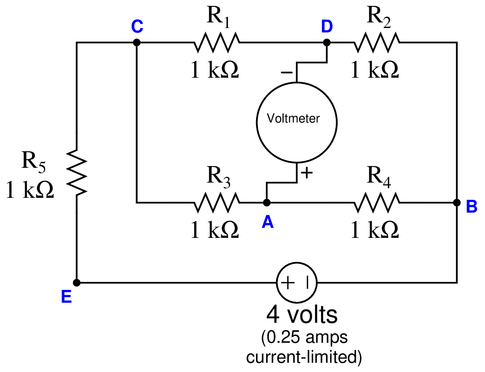
Suppose the voltmeter in this bridge circuit registers a strong negative voltage (note the test lead polarity +/- and consider that the voltage is negative, this means ‘-’ is at a higher voltage than ‘+’).
A test using a digital multimeter (DMM) shows the voltage between test points A and C to be 4 volts:
Identify the likelihood of each specified fault for this circuit. Consider each fault one at a time (i.e. no coincidental faults), determining whether or not each fault could independently account for all measurements and symptoms in this circuit.
$$\begin{array} {|l|l|} \hline Fault & Possible & Impossible \\ \hline R_1~Failed~open & & \\ \hline R_2~Failed~open & & \\ \hline R_3~Failed~open & & \\ \hline R_4~Failed~open & & \\ \hline R_5~Failed~open & & \\ \hline R_1~Failed~shorted & & \\ \hline R_2~Failed~shorted & & \\ \hline R_3~Failed~shorted & & \\ \hline R_4~Failed~shorted & & \\ \hline R_5~Failed~shorted & & \\ \hline Voltage~source~dead & & \\ \hline \end{array}$$
Reveal answer$$\begin{array} {|l|l|} \hline Fault & Possible & Impossible \\ \hline R_1~Failed~open & & \surd \\ \hline R_2~Failed~open & & \surd \\ \hline R_3~Failed~open & & \surd \\ \hline R_4~Failed~open & \surd & \\ \hline R_5~Failed~open & & \surd \\ \hline R_1~Failed~shorted & & \surd \\ \hline R_2~Failed~shorted & & \surd \\ \hline R_3~Failed~shorted & & \surd \\ \hline R_4~Failed~shorted & & \surd \\ \hline R_5~Failed~shorted & & \surd \\ \hline Voltage~source~dead & & \surd \\ \hline \end{array}$$
-
Question 8
Suppose the voltmeter in this bridge circuit registers a strong {\it positive} voltage. A test using a digital multimeter (DMM) shows the voltage between test points {\bf A} and {\bf B} to be 12 volts:

Identify the likelihood of each specified fault for this circuit. Consider each fault one at a time (i.e. no coincidental faults), determining whether or not each fault could independently account for all measurements and symptoms in this circuit.
$$\begin{array} {|l|l|} \hline Fault & Possible & Impossible \\ \hline R_1~Failed~open & & \\ \hline R_2~Failed~open & & \\ \hline R_3~Failed~open & & \\ \hline R_4~Failed~open & & \\ \hline R_1~Failed~shorted & & \\ \hline R_2~Failed~shorted & & \\ \hline R_3~Failed~shorted & & \\ \hline R_4~Failed~shorted & & \\ \hline Voltage~source~dead & & \\ \hline \end{array}$$
Reveal answer$$\begin{array} {|l|l|} \hline Fault & Possible & Impossible \\ \hline R_1~Failed~open & & \surd \\ \hline R_2~Failed~open & \surd & \\ \hline R_3~Failed~open & \surd & \\ \hline R_4~Failed~open & & \surd \\ \hline R_1~Failed~shorted & \surd & \\ \hline R_2~Failed~shorted & & \surd \\ \hline R_3~Failed~shorted & & \surd \\ \hline R_4~Failed~shorted & \surd & \\ \hline Voltage~source~dead & & \surd \\ \hline \end{array}$$
-
Question 9
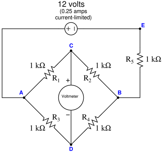
Suppose the voltmeter in this bridge circuit registers a strong {\it negative} voltage:

Identify the likelihood of each specified fault for this circuit. Consider each fault one at a time (i.e. no coincidental faults), determining whether or not each fault could independently account for all measurements and symptoms in this circuit.
$$\begin{array} {|l|l|} \hline Fault & Possible & Impossible \\ \hline R_1~Failed~open & & \\ \hline R_2~Failed~open & & \\ \hline R_3~Failed~open & & \\ \hline R_4~Failed~open & & \\ \hline R_1~Failed~shorted & & \\ \hline R_2~Failed~shorted & & \\ \hline R_3~Failed~shorted & & \\ \hline R_4~Failed~shorted & & \\ \hline Voltage~source~dead & & \\ \hline \end{array}$$
Reveal answer$$\begin{array} {|l|l|} \hline Fault & Possible & Impossible \\ \hline R_1~Failed~open & \surd & \\ \hline R_2~Failed~open & & \surd \\ \hline R_3~Failed~open & & \surd \\ \hline R_4~Failed~open & \surd & \\ \hline R_1~Failed~shorted & & \surd \\ \hline R_2~Failed~shorted & \surd & \\ \hline R_3~Failed~shorted & \surd & \\ \hline R_4~Failed~shorted & & \surd \\ \hline Voltage~source~dead & & \surd \\ \hline \end{array}$$
-
Question 10
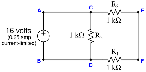
Suppose a voltmeter registers 22 volts between test points {\bf A} and {\bf D}:
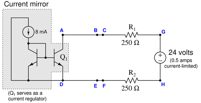
Identify the likelihood of each specified fault for this circuit. Consider each fault one at a time (i.e. no coincidental faults), determining whether or not each fault could independently account for all measurements and symptoms in this circuit.
$$\begin{array} {|l|l|} \hline Fault & Possible & Impossible \\ \hline R_1~Failed~open & & \\ \hline R_2~Failed~open & & \\ \hline Q_1~Failed~open & & \\ \hline R_1~Failed~shorted & & \\ \hline R_2~Failed~shorted & & \\ \hline Q_1~Failed~shorted & & \\ \hline Voltage~source~dead & & \\ \hline \end{array}$$
Reveal answer$$\begin{array} {|l|l|} \hline Fault & Possible & Impossible \\ \hline R_1~Failed~open & & \surd \\ \hline R_2~Failed~open & & \surd \\ \hline Q_1~Failed~open & & \surd \\ \hline R_1~Failed~shorted & \surd & \\ \hline R_2~Failed~shorted & \surd & \\ \hline Q_1~Failed~shorted & & \surd \\ \hline Voltage~source~dead & & \surd \\ \hline \end{array}$$
-
Question 11
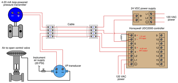
This pictorial diagram shows the wiring connections for a simple pressure control loop, where a loop-powered 4-20 mA pressure transmitter sends a signal to a Honeywell controller, which in turn sends another 4-20 mA signal to a control valve:

If an operator informs you that the pressure indicated by the Honeywell controller is below range (“pegged” full downscale, reading -10
Reveal answerIf the Honeywell controller is pegged downscale, it means the analog input is receiving too little voltage. A failed-open cable anywhere from the controller to the transmitter would do this, as would a dead DC power supply.
No fault in the valve (output) circuit would have any effect on the controller’s indication of pressure, since the valve control circuit is independent of the transmitter circuit.
-
Question 12
Suppose a voltmeter registers 6 volts between test points {\bf C} and {\bf D} while the pushbutton is released (not pressed), and also 6 volts between the same test points while the pushbutton is pressed:
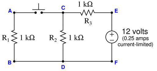
Identify the likelihood of each specified fault for this circuit. Consider each fault one at a time (i.e. no coincidental faults), determining whether or not each fault could independently account for all measurements and symptoms in this circuit.
$$\begin{array} {|l|l|} \hline Fault & Possible & Impossible \\ \hline Switch~Failed~open & & \\ \hline R_1~Failed~open & & \\ \hline R_2~Failed~open & & \\ \hline R_3~Failed~open & & \\ \hline Switch~Failed~shorted & & \\ \hline R_1~Failed~shorted & & \\ \hline R_2~Failed~shorted & & \\ \hline R_3~Failed~shorted & & \\ \hline Voltage~source~dead & & \\ \hline \end{array}$$
Reveal answer$$\begin{array} {|l|l|} \hline Fault & Possible & Impossible \\ \hline Switch~Failed~open & \surd & \\ \hline R_1~Failed~open & \surd & \\ \hline R_2~Failed~open & & \surd \\ \hline R_3~Failed~open & & \surd \\ \hline Switch~Failed~shorted & & \surd \\ \hline R_1~Failed~shorted & & \surd \\ \hline R_2~Failed~shorted & & \surd \\ \hline R_3~Failed~shorted & & \surd \\ \hline Voltage~source~dead & & \surd \\ \hline \end{array}$$
-
Question 13
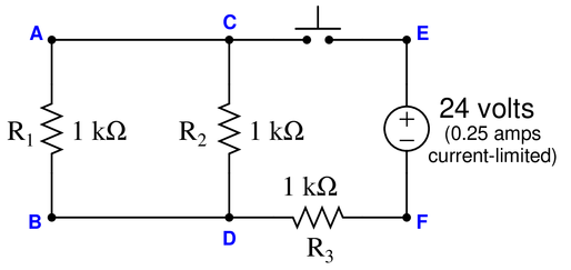
Suppose a voltmeter registers 24 volts between test points {\bf E} and {\bf C} while the pushbutton is released (not pressed), and 0 volts between test points {\bf A} and {\bf B} while the pushbutton is pressed:
Identify the likelihood of each specified fault for this circuit. Consider each fault one at a time (i.e. no coincidental faults), determining whether or not each fault could independently account for all measurements and symptoms in this circuit.
$$\begin{array} {|l|l|} \hline Fault & Possible & Impossible \\ \hline Switch~Failed~open & & \\ \hline R_1~Failed~open & & \\ \hline R_2~Failed~open & & \\ \hline R_3~Failed~open & & \\ \hline Switch~Failed~shorted & & \\ \hline R_1~Failed~shorted & & \\ \hline R_2~Failed~shorted & & \\ \hline R_3~Failed~shorted & & \\ \hline Voltage~source~dead & & \\ \hline \end{array}$$
Reveal answer$$\begin{array} {|l|l|} \hline Fault & Possible & Impossible \\ \hline Switch~Failed~open & \surd & \\ \hline R_1~Failed~open & & \surd \\ \hline R_2~Failed~open & & \surd \\ \hline R_3~Failed~open & \surd & \\ \hline Switch~Failed~shorted & & \surd \\ \hline R_1~Failed~shorted & \surd & \\ \hline R_2~Failed~shorted & \surd & \\ \hline R_3~Failed~shorted & & \surd \\ \hline Voltage~source~dead & & \surd \\ \hline \end{array}$$
-
Question 14
Suppose a voltmeter registers 0 volts between test points {\bf E} and {\bf F}, and 9 volts between test points {\bf F} and {\bf H} when the connection between {\bf F} and {\bf H} has been broken:

Identify the likelihood of each specified fault for this circuit. Consider each fault one at a time (i.e. no coincidental faults), determining whether or not each fault could independently account for all measurements and symptoms in this circuit.
$$\begin{array} {|l|l|} \hline Fault & Possible & Impossible \\ \hline R_1~Failed~open & & \\ \hline R_2~Failed~open & & \\ \hline R_3~Failed~open & & \\ \hline R_1~Failed~shorted & & \\ \hline R_2~Failed~shorted & & \\ \hline R_3~Failed~shorted & & \\ \hline Voltage~source~dead & & \\ \hline \end{array}$$
Reveal answer$$\begin{array} {|l|l|} \hline Fault & Possible & Impossible \\ \hline R_1~Failed~open & & \surd \\ \hline R_2~Failed~open & & \surd \\ \hline R_3~Failed~open & & \surd \\ \hline R_1~Failed~shorted & & \surd \\ \hline R_2~Failed~shorted & & \surd \\ \hline R_3~Failed~shorted & \surd & \\ \hline Voltage~source~dead & & \surd \\ \hline \end{array}$$
-
Question 15
Suppose a voltmeter registers 0 volts between test points {\bf B} and {\bf C}, and measures 24 volts between those same two test points after the connection has been broken between points {\bf A} and {\bf B}:

Identify the likelihood of each specified fault for this circuit. Consider each fault one at a time (i.e. no coincidental faults), determining whether or not each fault could independently account for all measurements and symptoms in this circuit.
$$\begin{array} {|l|l|} \hline Fault & Possible & Impossible \\ \hline R_1~Failed~open & & \\ \hline R_2~Failed~open & & \\ \hline R_3~Failed~open & & \\ \hline R_4~Failed~open & & \\ \hline R_1~Failed~shorted & & \\ \hline R_2~Failed~shorted & & \\ \hline R_3~Failed~shorted & & \\ \hline R_4~Failed~shorted & & \\ \hline Voltage~source~dead & & \\ \hline \end{array}$$
Reveal answer$$\begin{array} {|l|l|} \hline Fault & Possible & Impossible \\ \hline R_1~Failed~open & & \surd \\ \hline R_2~Failed~open & & \surd \\ \hline R_3~Failed~open & & \surd \\ \hline R_4~Failed~open & & \surd \\ \hline R_1~Failed~shorted & & \surd \\ \hline R_2~Failed~shorted & \surd & \\ \hline R_3~Failed~shorted & & \surd \\ \hline R_4~Failed~shorted & & \surd \\ \hline Voltage~source~dead & & \surd \\ \hline \end{array}$$
-
Question 16
Suppose a voltmeter registers 9 volts between test points {\bf B} and {\bf C}, but measures 18 volts between those same two test points after the connection has been broken between points {\bf E} and {\bf G}:

Identify the likelihood of each specified fault for this circuit. Consider each fault one at a time (i.e. no coincidental faults), determining whether or not each fault could independently account for all measurements and symptoms in this circuit.
$$\begin{array} {|l|l|} \hline Fault & Possible & Impossible \\ \hline R_1~Failed~open & & \\ \hline R_2~Failed~open & & \\ \hline R_3~Failed~open & & \\ \hline R_1~Failed~shorted & & \\ \hline R_2~Failed~shorted & & \\ \hline R_3~Failed~shorted & & \\ \hline Voltage~source~dead & & \\ \hline \end{array}$$
Reveal answer$$\begin{array} {|l|l|} \hline Fault & Possible & Impossible \\ \hline R_1~Failed~open & & \surd \\ \hline R_2~Failed~open & \surd & \\ \hline R_3~Failed~open & & \surd \\ \hline R_1~Failed~shorted & & \surd \\ \hline R_2~Failed~shorted & & \surd \\ \hline R_3~Failed~shorted & & \surd \\ \hline Voltage~source~dead & & \surd \\ \hline \end{array}$$
-
Question 17
Suppose a voltmeter registers 0 volts between test points {\bf A} and {\bf C}, and also measures 0 volts between those same two test points after the connection has been broken between points {\bf A} and {\bf B}:

Identify the likelihood of each specified fault for this circuit. Consider each fault one at a time (i.e. no coincidental faults), determining whether or not each fault could independently account for all measurements and symptoms in this circuit.
$$\begin{array} {|l|l|} \hline Fault & Possible & Impossible \\ \hline R_1~Failed~open & & \\ \hline R_2~Failed~open & & \\ \hline R_3~Failed~open & & \\ \hline R_1~Failed~shorted & & \\ \hline R_2~Failed~shorted & & \\ \hline R_3~Failed~shorted & & \\ \hline Voltage~source~dead & & \\ \hline \end{array}$$
Reveal answer$$\begin{array} {|l|l|} \hline Fault & Possible & Impossible \\ \hline R_1~Failed~open & \surd & \\ \hline R_2~Failed~open & & \surd \\ \hline R_3~Failed~open & & \surd \\ \hline R_1~Failed~shorted & & \surd \\ \hline R_2~Failed~shorted & & \surd \\ \hline R_3~Failed~shorted & & \surd \\ \hline Voltage~source~dead & \surd & \\ \hline \end{array}$$
-
Question 18
Suppose an ammeter inserted between test point {\bf C} and the nearest lead of resistor R_2 registers 0 mA in this series-parallel circuit:

Identify the likelihood of each specified fault for this circuit. Consider each fault one at a time (i.e. no coincidental faults), determining whether or not each fault could independently account for all measurements and symptoms in this circuit.
$$\begin{array} {|l|l|} \hline Fault & Possible & Impossible \\ \hline R_1~Failed~open & & \\ \hline R_2~Failed~open & & \\ \hline R_3~Failed~open & & \\ \hline R_4~Failed~open & & \\ \hline R_1~Failed~shorted & & \\ \hline R_2~Failed~shorted & & \\ \hline R_3~Failed~shorted & & \\ \hline R_4~Failed~shorted & & \\ \hline Current~source~dead & & \\ \hline \end{array}$$
Reveal answer$$\begin{array} {|l|l|} \hline Fault & Possible & Impossible \\ \hline R_1~Failed~open & \surd & \\ \hline R_2~Failed~open & \surd & \\ \hline R_3~Failed~open & & \surd \\ \hline R_4~Failed~open & & \surd \\ \hline R_1~Failed~shorted & & \surd \\ \hline R_2~Failed~shorted & & \surd \\ \hline R_3~Failed~shorted & & \surd \\ \hline R_4~Failed~shorted & & \surd \\ \hline Current~source~dead & \surd & \\ \hline \end{array}$$
-
Question 19
Suppose an ammeter inserted between test point {\bf F} and the nearest lead of resistor R_4 registers 0 mA in this series-parallel circuit:

Identify the likelihood of each specified fault for this circuit. Consider each fault one at a time (i.e. no coincidental faults), determining whether or not each fault could independently account for all measurements and symptoms in this circuit.
$$\begin{array} {|l|l|} \hline Fault & Possible & Impossible \\ \hline R_1~Failed~open & & \\ \hline R_2~Failed~open & & \\ \hline R_3~Failed~open & & \\ \hline R_4~Failed~open & & \\ \hline R_1~Failed~shorted & & \\ \hline R_2~Failed~shorted & & \\ \hline R_3~Failed~shorted & & \\ \hline R_4~Failed~shorted & & \\ \hline Current~source~dead & & \\ \hline \end{array}$$
Reveal answer$$\begin{array} {|l|l|} \hline Fault & Possible & Impossible \\ \hline R_1~Failed~open & \surd & \\ \hline R_2~Failed~open & & \surd \\ \hline R_3~Failed~open & \surd & \\ \hline R_4~Failed~open & \surd & \\ \hline R_1~Failed~shorted & & \surd \\ \hline R_2~Failed~shorted & \surd & \\ \hline R_3~Failed~shorted & & \surd \\ \hline R_4~Failed~shorted & & \surd \\ \hline Current~source~dead & \surd & \\ \hline \end{array}$$
-
Question 20
Suppose a voltmeter registers 0 volts between test points {\bf A} and {\bf D} in this series-parallel circuit:

Determine the diagnostic value of each of the following tests. Assume only one fault in the system, including any single component or any single wire/cable/tube connecting components together. If a proposed test could provide new information to help you identify the location and/or nature of the one fault, mark “yes.” Otherwise, if a proposed test would not reveal anything relevant to identifying the fault (already discernible from the measurements and symptoms given so far), mark “no.’‘
$$\begin{array} {|l|l|} \hline Diagnostic~test & Yes & No \\ \hline Measure~V_{CD}~with~power~applied & & \\ \hline Measure~V_{DF}~with~power~applied & & \\ \hline Measure~V_{DE}~with~power~applied & & \\ \hline Measure~I_{R1}~with~power~applied & & \\ \hline Measure~I_{R2}~with~power~applied & & \\ \hline Measure~R_{AB}~with~source~disconnected~from~C & & \\ \hline Measure~R_{DF}~with~source~disconnected~from~E & & \\ \hline Measure~R_{CF}~with~source~disconnected~from~C & & \\ \hline Measure~R_{CD}~with~wire~disconnected~between~{\bf A} and C & & \\ \hline Measure~R_{CD}$ with R_3 disconnected from D & & \\ \hline \end{array}$$
Reveal answer$$\begin{array} {|l|l|} \hline Diagnostic~test & Yes & No \\ \hline Measure~V_{CD}~with~power~applied & \surd & \\ \hline Measure~V_{DF}~with~power~applied & \surd & \\ \hline Measure~V_{DE}~with~power~applied & \surd & \\ \hline Measure~I_{R1}~with~power~applied & \surd & \\ \hline Measure~I_{R2}~with~power~applied & \surd & \\ \hline Measure~R_{AB}~with~source~disconnected~from~C & \surd & \\ \hline Measure~R_{DF}~with~source~disconnected~from~E & \surd & \\ \hline Measure~R_{CF}~with~source~disconnected~from~C & \surd & \\ \hline Measure~R_{CD}~with~wire~disconnected~between~{\bf A} and C & & \surd \\ \hline Measure~R_{CD}$ with R_3 disconnected from D & \surd & \\ \hline \end{array}$$
-
Question 21
Suppose an operator discovers that the natural gas make-up valve in this fuel gas pressure control system is shut when the controller output is 78

{\bullet} Test 1: Measured 18.6 volts DC between PT-528 transmitter terminals.
{\bullet} Test 2: Measured supply air pressure at PV-528a to be 22 PSIG.
{\bullet} Test 3: Measured 0 volts DC between terminals 25 and 26.
{\bullet} Test 4: Measured 27 volts DC between terminals 5 and 6.
{\bullet} Test 5: Measured 27 volts DC between terminals 19 and 20.
{\bullet} Test 6: Measured 27 volts DC between terminals 15 and 16.
Identify any useful information about the nature or location of the fault derived from the results of each test, in order of the tests performed. If the test is not useful (i.e. provides no new information), mark it as such. Assuming there is only one fault in the circuit, identify the location and nature of the fault as precisely as you can from the test results shown above.
Reveal answer{\bullet} Test 1: Measured 18.6 volts DC between PT-528 transmitter terminals. Proves nothing that is helpful in diagnosing the valve problem. We know the transmitter has adequate power to function, but this tells us nothing about why the make-up valve refuses to open.
{\bullet} Test 2: Measured supply air pressure at PV-528a to be 22 PSIG. Proves that the air supply to the make-up valve is good (needs to be more than 15 PSI for a 3-15 PSI bench-set valve). However, we don’t know anything more about the fault other than the fact it isn’t this one thing.
{\bullet} Test 3: Measured 0 volts DC between terminals 25 and 26. Proves the fault is electrical in nature: either an “open” between these terminals and the DCS output, or a “short” potentially anywhere in this cable (or in the I/P) for valve PV-528a.
{\bullet} Test 4: Measured 27 volts DC between terminals 5 and 6. Proves the fault must be an “open” somewhere between these terminals and terminals 25-26.
{\bullet} Test 5: Measured 27 volts DC between terminals 19 and 20. This is an unnecessary test, as we already know there will be full voltage here, since points “downstream” of these (i.e. closer to the load) have full voltage.
{\bullet} Test 6: Measured 27 volts DC between terminals 15 and 16. Proves the fault must be an “open” between these terminals and terminals 25-26.
The fault is an “open” in wire pair 5 of cable MOLSV-10, or at the connection point between one of these wires and the terminal block.
-
Question 22
This reversing motor control circuit has a problem: it runs just fine in reverse, but not at all in the forward direction. A technician begins diagnosing the circuit, following the steps shown (in order):
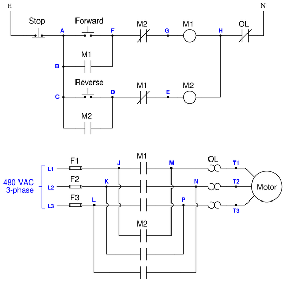
{\bullet} Test 1: Jumpered points {\bf F} and {\bf G} while pressing the “Forward” pushbutton. Motor did not turn.
{\bullet} Test 2: Measured 117 VAC between points {\bf G} and {\bf H} while pressing “Forward” pushbutton.
{\bullet} Test 3: Measured 478 VAC between points {\bf M} and {\bf N} while pressing “Forward” pushbutton.
{\bullet} Test 4: Measured 239 VAC between points {\bf M} and {\bf P} while pressing “Forward” pushbutton.
{\bullet} Test 5: Measured 239 VAC between points {\bf N} and {\bf P} while pressing “Forward” pushbutton.
Identify any useful information about the nature or location of the fault derived from the results of each test, in order of the tests performed. If the test is not useful (i.e. provides no new information), mark it as such. Assuming there is only one fault in the circuit, identify the location and nature of the fault as precisely as you can from the test results shown above.
Reveal answer{\bullet} Test 1: Jumpered points {\bf F} and {\bf G} while pressing the “Forward” pushbutton. Motor does not turn. While not a very efficient test, it does prove the problem is not an “open” M2 auxiliary contact.
{\bullet} Test 2: Measured 117 VAC between points {\bf G} and {\bf H} while pressing “Forward” pushbutton. This proves the M1 coil is indeed receiving control power when it should. Potential faults include an “open” M1 coil, or an “open” fault in the M1 power contacts.
{\bullet} Test 3: Measured 478 VAC between points {\bf M} and {\bf N} while pressing “Forward” pushbutton. Proves at those two power contacts are closing as they should.
{\bullet} Test 4: Measured 239 VAC between points {\bf M} and {\bf P} while pressing “Forward” pushbutton. Proves we do not have a good connection to line L3 through the third contact in the three-phase contactor. The reduced voltage (239 volts versus 478 volts) is due to the motor’s three-phase stator winding acting as a voltage divider, splitting the single-phase 478 VAC reading into two halves ($V_{MP}$ and $V_{NP}$).
{\bullet} Test 5: Measured 239 VAC between points {\bf N} and {\bf P} while pressing “Forward” pushbutton. Proves again that we do not have a good connection to line L3 through the third contact. Strictly speaking, this test is unnecessary. However, since the conclusion drawn from Test 4 is not that obvious, this test would not be a bad idea simply to clarify the fact that the 478 VAC reading between M and N is being split in half.
The fault is an “open” between L and P (one of the power contacts within contactor M1).
-
Question 23
This conveyor belt control circuit has a problem. The siren energizes when the “Start” pushbutton is pressed, but the conveyor belt never moves. The siren remains energized until the “Stop” button is pressed. A technician begins diagnosing the circuit, following the steps shown (in order). His first action is to press the “Start” switch so that the siren is continuously activated, before he begins any diagnostic tests:

{\bullet} Test 1: Measured 120 VAC between points {\bf A} and {\bf E}.
{\bullet} Test 2: Measured 120 VAC between points {\bf N} and {\bf L}.
{\bullet} Test 3: Measured 0 VAC between points {\bf J} and {\bf K}.
{\bullet} Test 4: Measured 0 VAC between points {\bf D} and {\bf M}.
{\bullet} Test 5: Measured 120 VAC between points {\bf A} and {\bf D}.
Identify any useful information about the nature or location of the fault derived from the results of each test, in order of the tests performed. If the test is not useful (i.e. provides no new information), mark it as such. Assuming there is only one fault in the circuit, identify the location and nature of the fault as precisely as you can from the test results shown above.
Reveal answer{\bullet} Test 1: Measured 120 VAC between points {\bf A} and {\bf E}. This is an unnecessary test, as we already know there is 120 VAC power available to the control circuit (otherwise, the siren would never energize).
{\bullet} Test 2: Measured 120 VAC between points {\bf N} and {\bf L}. This confirms the time-delay relay coil is receiving power, limiting the fault to either an “open” TD1 coil, or an “open” somewhere between points B and M.
{\bullet} Test 3: Measured 0 VAC between points {\bf J} and {\bf K}. This is an unnecessary test, as we already know NC contact M1 is closed, because the siren is being energized.
{\bullet} Test 4: Measured 0 VAC between points {\bf D} and {\bf M}. This proves no power is getting to the M1 contactor coil, indicating an “open” fault somewhere between B and M other than the coil itself.
{\bullet} Test 5: Measured 120 VAC between points {\bf A} and {\bf D}. This test alone proves an “open” fault must exist between points A and D. Combined with knowledge that the siren is latching on, we know the “open” fault cannot lie between A and B, and therefore must lie somewhere between B and D.
The fault is an “open,” either between B and contact TD1, at contact TD1 itself, or between points C and D.
-
Question 24
This air compressor control circuit has a problem. The air compressor refuses to start even when the air pressure is zero PSI. A technician begins diagnosing the circuit, following the steps shown (in order):
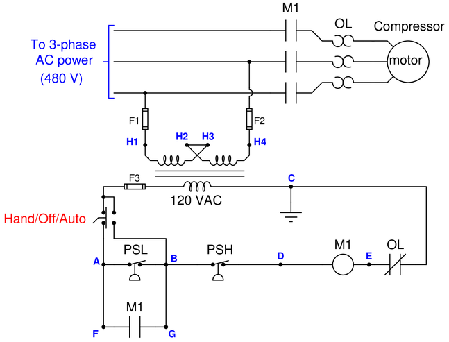
{\bullet} {\bf Test 1:} Measured 120 VAC between points {\bf A} and {\bf C}, with “Hand/Off/Auto” switch in the “Auto” position.
{\bullet} {\bf Test 2:} Measured 120 VAC between points {\bf A} and {\bf D}, with “Hand/Off/Auto” switch in “Auto” position.
{\bullet} {\bf Test 3:} Measured 0 VAC between points {\bf E} and {\bf C}, with “Hand/Off/Auto” switch in “Auto” position.
{\bullet} {\bf Test 4:} Jumpered points {\bf A} and {\bf B}, with “Hand/Off/Auto” switch in “Auto” position. The motor did not start.
Identify any useful information about the nature or location of the fault derived from the results of each test, in order of the tests performed. If the test is not useful (i.e. provides no new information), mark it as such. Assuming there is only one fault in the circuit, identify the location and nature of the fault as precisely as you can from the test results shown above.
Reveal answer{\bullet} {\bf Test 1:} Measured 120 VAC between points {\bf A} and {\bf C}, with “Hand/Off/Auto” switch in the “Auto” position. Proves there is 120 VAC control power available, that the fuse is good, and that the Hand/Off/Auto switch is passing power through to point A.
{\bullet} {\bf Test 2:} Measured 120 VAC between points {\bf A} and {\bf D}, with “Hand/Off/Auto” switch in “Auto” position. Proves there is an “open” fault somewhere between those points, in one of the two switches, and that we do not have any other “open” faults in the contactor coil circuit.
{\bullet} {\bf Test 3:} Measured 0 VAC between points {\bf E} and {\bf C}, with “Hand/Off/Auto” switch in “Auto” position. This is an unnecessary test, as we already know there is continuity through the overload contact.
{\bullet} {\bf Test 4:} Jumpered points {\bf A} and {\bf B}, with “Hand/Off/Auto” switch in “Auto” position. The motor did not start. Combined with the results of previous tests, this test proves the “open” fault must lie between points B and D: namely the PSH.
The fault is an “open” high pressure switch (PSH), or in the wires connecting the PSH to points B and D.
Notes:This question is a good candidate for a “Virtual Troubleshooting” exercise. Presenting the diagram to students, you first imagine in your own mind a particular fault in the system. Then, you present one or more symptoms of that fault (something noticeable by an operator or other user of the system). Students then propose various diagnostic tests to perform on this system to identify the nature and location of the fault, as though they were technicians trying to troubleshoot the problem. Your job is to tell them what the result(s) would be for each of the proposed diagnostic tests, documenting those results where all the students can see.
During and after the exercise, it is good to ask students follow-up questions such as:
{\bullet} What does the result of the last Diagnostic~test tell you about the fault?
{\bullet} Suppose the results of the last Diagnostic~test were different. What then would that result tell you about the fault?
{\bullet} Is the last Diagnostic~test the best one we could do?
{\bullet} What would be the ideal order of tests, to diagnose the problem in as few steps as possible? -
Question 25
Suppose the electric motor refuses to run when the “Run” pushbutton switch is pressed, whether the speed switch is set to “Fast” or to “Slow.” A technician begins diagnosing the circuit, following the steps shown (in order):
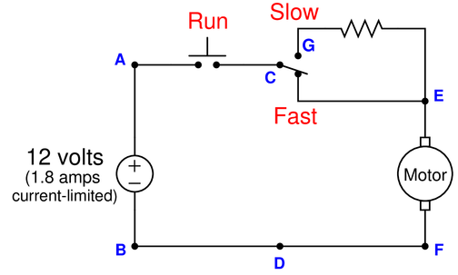
{\bullet} {\bf Test 1:} Measured 12 volts DC between points {\bf A} and {\bf B}, with “Run” switch pressed and speed switch in “Fast” position.
{\bullet} {\bf Test 2:} Measured 0 volts DC between points {\bf A} and {\bf C}, with “Run” switch unpressed and speed switch in “Fast” position.
{\bullet} {\bf Test 3:} Measured 12 volts DC between points {\bf G} and {\bf D}, with “Run” switch pressed and speed switch in “Fast” position.
{\bullet} {\bf Test 4:} Measured 25 ohms between points {\bf G} and {\bf E}, with “Run” switch unpressed and speed switch in “Fast” position.
{\bullet} {\bf Test 5:} Measured 12 volts DC between points {\bf A} and {\bf F}, with “Run” switch pressed and speed switch in “Fast” position.
Identify any useful information about the nature or location of the fault derived from the results of each test, in order of the tests performed. If the test is not useful (i.e. provides no new information), mark it as such. Assuming there is only one fault in the circuit, identify the location and nature of the fault as precisely as you can from the test results shown above.
Reveal answer{\bullet} {\bf Test 1:} Measured 12 volts DC between points {\bf A} and {\bf B}, with “Run” switch pressed and speed switch in “Fast” position. Proves that the source is not dead.
{\bullet} {\bf Test 2:} Measured 0 volts DC between points {\bf A} and {\bf C}, with “Run” switch unpressed and speed switch in “Fast” position. Proves that the “Run” switch is not~Failed~open (assuming only one fault).
{\bullet} {\bf Test 3:} Measured 12 volts DC between points {\bf G} and {\bf D}, with “Run” switch pressed and speed switch in “Fast” position. Eliminates any “open” faults except for the motor and the wire between D and F—fault must be in either of those two locations.
{\bullet} {\bf Test 4:} Measured 25 ohms between points {\bf G} and {\bf E}, with “Run” switch unpressed and speed switch in “Fast” position. This is an unnecessary test, because we already knew the resistor was not~Failed~open from test 3, and also because we know that the fault must be common to both speed switch positions and not just one (since the motor refuses to run in either the “Fast” or the “Slow” position.
{\bullet} {\bf Test 5:} Measured 12 volts DC between points {\bf A} and {\bf F}, with “Run” switch pressed and speed switch in “Fast” position. Proves the wire from D to F is not open. Combined with the results of previous tests, we can only conclude that the fault must lie within the motor.
The fault is an “open” electric motor.
-
Question 26
Suppose the electric motor refuses to run when the “Run” pushbutton switch is pressed. A technician begins diagnosing the circuit, following the steps shown (in order):

{\bullet} {\bf Test 1:} Measured 0 volts DC between points {\bf C} and {\bf D}, with “Run” switch pressed.
{\bullet} {\bf Test 2:} Measured 0 volts DC between points {\bf A} and {\bf C}, with “Run” switch unpressed.
{\bullet} {\bf Test 3:} Measured 12 volts DC between points {\bf A} and {\bf B}, with “Run” switch pressed.
{\bullet} {\bf Test 4:} Measured 12 volts DC between points {\bf C} and {\bf B}, with “Run” switch unpressed.
{\bullet} {\bf Test 5:} Measured 3.5 ohms between points {\bf E} and {\bf F}, with “Run” switch unpressed.
Identify any useful information about the nature or location of the fault derived from the results of each test, in order of the tests performed. If the test is not useful (i.e. provides no new information), mark it as such. Assuming there is only one fault in the circuit, identify the location and nature of the fault as precisely as you can from the test results shown above.
Reveal answer{\bullet} {\bf Test 1:} Measured 0 volts DC between points {\bf C} and {\bf D}, with “Run” switch pressed. Proves that the problem is to the left of these test points (toward the source). Most likely either a dead source or an “open” fault.
{\bullet} {\bf Test 2:} Measured 0 volts DC between points {\bf A} and {\bf C}, with “Run” switch unpressed. Proves the problem is not the switch (assuming only one fault).
{\bullet} {\bf Test 3:} Measured 12 volts DC between points {\bf A} and {\bf B}, with “Run” switch pressed. Proves the source is not dead.
{\bullet} {\bf Test 4:} Measured 12 volts DC between points {\bf C} and {\bf B}, with “Run” switch unpressed. This is an unnecessary test, as we already know the source is not dead and the switch is not failed open.
{\bullet} {\bf Test 5:} Measured 3.5 ohms between points {\bf E} and {\bf F}, with “Run” switch unpressed. This is an unnecessary test, as we already know the fault does not lie with the motor (assuming a single fault).
The fault is an “open,” between points B and D.
-
Question 27
Suppose the electric motor refuses to run when the “Run” pushbutton switch is pressed. A technician begins diagnosing the circuit, following the steps shown (in order):

{\bullet} {\bf Test 1:} Measured 2.8 ohms between points {\bf E} and {\bf F}, with “Run” switch unpressed.
{\bullet} {\bf Test 2:} Measured 12 volts between points {\bf A} and {\bf F}, with “Run” switch unpressed.
{\bullet} {\bf Test 3:} Measured 12 volts between points {\bf A} and {\bf B}, with “Run” switch unpressed.
{\bullet} {\bf Test 4:} Measured 12 volts between points {\bf A} and {\bf C}, with “Run” switch pressed.
Identify any useful information about the nature or location of the fault derived from the results of each test, in order of the tests performed. If the test is not useful (i.e. provides no new information), mark it as such. Assuming there is only one fault in the circuit, identify the location and nature of the fault as precisely as you can from the test results shown above.
Reveal answer{\bullet} {\bf Test 1:} Measured 2.8 ohms between points {\bf E} and {\bf F}, with “Run” switch unpressed. Proves that the motor is not open, and likely not shorted either.
{\bullet} {\bf Test 2:} Measured 12 volts between points {\bf A} and {\bf F}, with “Run” switch unpressed. Proves that the source is not dead, and that the wires connecting B to D to F are all good.
{\bullet} {\bf Test 3:} Measured 12 volts between points {\bf A} and {\bf B}, with “Run” switch unpressed. This is an unnecessary test, as we already know the source is not dead.
{\bullet} {\bf Test 4:} Measured 12 volts between points {\bf A} and {\bf C}, with “Run” switch pressed. Proves that the switch is failed open, as it should drop 0 volts when pressed!
The fault is an “open” pushbutton switch.
-
Question 28
This pictorial diagram shows the wiring connections for a simple pressure control loop, where a loop-powered 4-20 mA pressure transmitter sends a signal to a Honeywell controller, which in turn sends another 4-20 mA signal to a control valve:
Suppose the operator informs you that the control valve refuses to open, no matter what value she sets the output of the controller in manual mode. Your job now is to diagnose the problem in this control loop using only basic test equipment (e.g. digital multimeter, hand tools).
Determine the diagnostic value of each of the following tests. Assume only one fault in the system, including any single component or any single wire/cable/tube connecting components together. If a proposed test could provide new information to help you identify the location and/or nature of the one fault, mark “yes.” Otherwise, if a proposed test would not reveal anything relevant to identifying the fault (already discernible from the measurements and symptoms given so far), mark “no.’‘
$$\begin{array} {|l|l|} \hline Diagnostic~test & Yes & No \\ \hline Place~controller~in~auto~mode & & \\ \hline Measure~V_{AB}~with~output~set~to~100 & & \\ \hline Measure~V_{5-4}~with~output~set~to~100 & & \\ \hline Measure~V_{8-7}~with~output~set~to~50 & & \\ \hline Crack~open~fitting~at~‘S’~port~on~I/P~transducer & & \\ \hline Crack~open~fitting~at~‘O’~port~on~I/P~transducer & & \\ \hline Press~I/P~transducer’s~flapper~closer~to~nozzle & & \\ \hline Pull~I/P~transducer’s~flapper~away~from~nozzle & & \\ \hline Tighten~nuts~compressing~the~valve~stem~packing & & \\ \hline Loosen~nuts~compressing~the~valve~stem~packing & & \\ \hline Measure~output~voltage~of~DC~power~supply & & \\ \hline Measure~voltage~across~pressure~transmitter~terminals & & \\ \hline Measure~voltage~across~I/P~transducer~terminals & & \\ \hline \end{array}$$
Reveal answer$$\begin{array} {|l|l|} \hline Diagnostic~test & Yes & No \\ \hline Place~controller~in~auto~mode & & \surd \\ \hline Measure~V_{AB}~with~output~set~to~100 & & \\ \hline Measure~V_{5-4}~with~output~set~to~100 & & \\ \hline Measure~V_{8-7}~with~output~set~to~50 & & \\ \hline Crack~open~fitting~at~‘S’~port~on~I/P~transducer & \surd & \\ \hline Crack~open~fitting~at~‘O’~port~on~I/P~transducer & \surd & \\ \hline Press~I/P~transducer’s~flapper~closer~to~nozzle & \surd & \\ \hline Pull~I/P~transducer’s~flapper~away~from~nozzle & & \surd \\ \hline Tighten~nuts~compressing~the~valve~stem~packing & & \surd \\ \hline Loosen~nuts~compressing~the~valve~stem~packing & & \\ \hline Measure~output~voltage~of~DC~power~supply & & \surd \\ \hline Measure~voltage~across~pressure~transmitter~terminals & & \surd \\ \hline Measure~voltage~across~I/P~transducer~terminals & \surd & \\ \hline \end{array}$$
-
Question 29
Suppose a voltmeter registers 0 volts between test points {\bf E} and {\bf F} in this circuit:

Determine the diagnostic value of each of the following tests. Assume only one fault in the system, including any single component or any single wire/cable/tube connecting components together. If a proposed test could provide new information to help you identify the location and/or nature of the one fault, mark “yes.” Otherwise, if a proposed test would not reveal anything relevant to identifying the fault (already discernible from the measurements and symptoms given so far), mark “no.’‘
$$\begin{array} {|l|l|} \hline Diagnostic~test & Yes & No \\ \hline Measure~V_{AC}~with~power~applied & & \\ \hline Measure~V_{JK}~with~power~applied & & \\ \hline Measure~V_{CK}~with~power~applied & & \\ \hline Measure~I_{R1}~with~power~applied & & \\ \hline Measure~I_{R2}~with~power~applied & & \\ \hline Measure~I_{R3}~with~power~applied & & \\ \hline Measure~R_{AC}~with~source~disconnected~from~R_1 & & \\ \hline Measure~R_{DF}~with~source~disconnected~from~R_1 & & \\ \hline Measure~R_{EG}~with~source~disconnected~from~R_1 & & \\ \hline Measure~R_{HK}~with~source~disconnected~from~R_1 & & \\ \hline \end{array}$$
Reveal answer$$\begin{array} {|l|l|} \hline Diagnostic~test & Yes & No \\ \hline Measure~V_{AC}~with~power~applied & \surd & \\ \hline Measure~V_{JK}~with~power~applied & & \surd \\ \hline Measure~V_{CK}~with~power~applied & \surd & \\ \hline Measure~I_{R1}~with~power~applied & \surd & \\ \hline Measure~I_{R2}~with~power~applied & \surd & \\ \hline Measure~I_{R3}~with~power~applied & \surd & \\ \hline Measure~R_{AC}~with~source~disconnected~from~R_1 & \surd & \\ \hline Measure~R_{DF}~with~source~disconnected~from~R_1 & \surd & \\ \hline Measure~R_{EG}~with~source~disconnected~from~R_1 & & \surd \\ \hline Measure~R_{HK}~with~source~disconnected~from~R_1 & & \surd \\ \hline \end{array}$$
-
Question 30
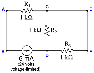
Suppose a voltmeter registers 24 volts between test points {\bf A} and {\bf B} in this series-parallel circuit:

Identify the likelihood of each specified fault for this circuit. Consider each fault one at a time (i.e. no coincidental faults), determining whether or not each fault could independently account for all measurements and symptoms in this circuit.
$$\begin{array} {|l|l|} \hline Fault & Possible & Impossible \\ \hline R_1~Failed~open & & \\ \hline R_2~Failed~open & & \\ \hline R_3~Failed~open & & \\ \hline R_4~Failed~open & & \\ \hline R_1~Failed~shorted & & \\ \hline R_2~Failed~shorted & & \\ \hline R_3~Failed~shorted & & \\ \hline R_4~Failed~shorted & & \\ \hline Current~source~dead & & \\ \hline \end{array}$$
Reveal answer$$\begin{array} {|l|l|} \hline Fault & Possible & Impossible \\ \hline R_1~Failed~open & \surd & \\ \hline R_2~Failed~open & & \surd \\ \hline R_3~Failed~open & & \surd \\ \hline R_4~Failed~open & & \surd \\ \hline R_1~Failed~shorted & & \surd \\ \hline R_2~Failed~shorted & & \surd \\ \hline R_3~Failed~shorted & & \surd \\ \hline R_4~Failed~shorted & & \surd \\ \hline Current~source~dead & & \surd \\ \hline \end{array}$$
-
Question 31
Suppose a voltmeter registers 16 volts between test points {\bf C} and {\bf E} in this series-parallel circuit:
Determine the diagnostic value of each of the following tests. Assume only one fault in the system, including any single component or any single wire/cable/tube connecting components together. If a proposed test could provide new information to help you identify the location and/or nature of the one fault, mark “yes.” Otherwise, if a proposed test would not reveal anything relevant to identifying the fault (already discernible from the measurements and symptoms given so far), mark “no.’‘
$$\begin{array} {|l|l|} \hline Diagnostic~test & Yes & No \\ \hline Measure~V_{CD}~with~power~applied & & \\ \hline Measure~V_{DF}~with~power~applied & & \\ \hline Measure~I_{R1}~with~power~applied & & \\ \hline Measure~I_{R2}~with~power~applied & & \\ \hline Measure~R_{AB}~with~power~applied & & \\ \hline Measure~R_{DF}~with~power~applied & & \\ \hline Measure~R_{CF}~with~power~applied & & \\ \hline Measure~R_{AB}~with~source~disconnected~from~A & & \\ \hline Measure~R_{DF}~with~source~disconnected~from~A & & \\ \hline Measure~R_{CF}~with~source~disconnected~from~B & & \\ \hline Measure~R_{CF}~with~wire~disconnected~between~A and {\bf C} & & \\ \hline \end{array}$$
Reveal answer$$\begin{array} {|l|l|} \hline Diagnostic~test & Yes & No \\ \hline Measure~V_{CD}~with~power~applied & & \surd \\ \hline Measure~V_{DF}~with~power~applied & & \surd \\ \hline Measure~I_{R1}~with~power~applied & \surd & \\ \hline Measure~I_{R2}~with~power~applied & & \surd \\ \hline Measure~R_{AB}~with~power~applied & & \surd \\ \hline Measure~R_{DF}~with~power~applied & \surd & \\ \hline Measure~R_{CF}~with~power~applied & & \surd \\ \hline Measure~R_{AB}~with~source~disconnected~from~A & \surd & \\ \hline Measure~R_{DF}~with~source~disconnected~from~A & \surd & \\ \hline Measure~R_{CF}~with~source~disconnected~from~B & \surd & \\ \hline Measure~R_{CF}~with~wire~disconnected~between~A and {\bf C} & \surd & \\ \hline \end{array}$$
-
Question 32
Suppose the lamp refuses to light up when the pushbutton switch is pressed. A voltmeter registers 0 volts between test points {\bf A} and {\bf D} in the circuit while the pushbutton is pressed:

Determine the diagnostic value of each of the following tests. Assume only one fault in the system, including any single component or any single wire/cable/tube connecting components together. If a proposed test could provide new information to help you identify the location and/or nature of the one fault, mark “yes.” Otherwise, if a proposed test would not reveal anything relevant to identifying the fault (already discernible from the measurements and symptoms given so far), mark “no.’‘
$$\begin{array} {|l|l|} \hline Diagnostic~test & Yes & No \\ \hline Measure~V_{EF}~with~switch~pressed & & \\ \hline Measure~V_{CD}~with~switch~pressed & & \\ \hline Measure~V_{CB}~with~switch~pressed & & \\ \hline Measure~V_{CE}~with~switch~pressed & & \\ \hline Measure~R_{AB}~with~switch~pressed & & \\ \hline Measure~V_{EF}~with~switch~unpressed & & \\ \hline Measure~V_{CD}~with~switch~unpressed & & \\ \hline Measure~V_{CB}~with~switch~unpressed & & \\ \hline Measure~V_{CE}~with~switch~unpressed & & \\ \hline Measure~R_{AB}~with~switch~unpressed & & \\ \hline \end{array}$$
Reveal answer$$\begin{array} {|l|l|} \hline Diagnostic~test & Yes & No \\ \hline Measure~V_{EF}~with~switch~pressed & \surd & \\ \hline Measure~V_{CD}~with~switch~pressed & \surd & \\ \hline Measure~V_{CB}~with~switch~pressed & \surd & \\ \hline Measure~V_{CE}~with~switch~pressed & \surd & \\ \hline Measure~R_{AB}~with~switch~pressed & \surd & \\ \hline Measure~V_{EF}~with~switch~unpressed & \surd & \\ \hline Measure~V_{CD}~with~switch~unpressed & & \surd \\ \hline Measure~V_{CB}~with~switch~unpressed & & \surd \\ \hline Measure~V_{CE}~with~switch~unpressed & \surd & \\ \hline Measure~R_{AB}~with~switch~unpressed & \surd & \\ \hline \end{array}$$
-
Question 33
Suppose the lamp refuses to light up. A voltmeter registers 24 volts between test points {\bf C} and {\bf D}:

First, list all the possible (single) faults that could account for all measurements and symptoms in this circuit, including failed wires as well as failed components:
Now, determine the diagnostic value of each of the following tests, based on the faults you listed above. If a proposed test could provide new information to help you identify the location and/or nature of the one fault, mark “yes.” Otherwise, if a proposed test would not reveal anything relevant to identifying the fault (already discernible from the measurements and symptoms given so far), mark “no.’‘
$$\begin{array} {|l|l|} \hline Diagnostic~test & Yes & No \\ \hline Measure~V_{CF}$ & & \\ \hline Measure~V_{ED}$ & & \\ \hline Measure~V_{AB}$ & & \\ \hline Measure~V_{AD}$ & & \\ \hline Measure~V_{CB}$ & & \\ \hline Measure~V_{EF}$ & & \\ \hline Measure current through wire connecting A and C & & \\ \hline Jumper A and C together & & \\ \hline Jumper B and D together & & \\ \hline Jumper A and B together & & \\ \hline \end{array}$$
Reveal answerHere is a comprehensive list of faults, each one individually capable of accounting for the symptom (no light) and the measurement of 24 volts between {\bf C} and {\bf D}:
{\bullet} Lamp burned out (failed open)
{\bullet} Wire~Failed~open between {\bf A} and {\bf C}
{\bullet} Wire~Failed~open between {\bf B} and {\bf D}Based on this short list of possible faults—assuming only {\it one} of them is actually true—the value of each proposed test is as follows:
$$\begin{array} {|l|l|} \hline Diagnostic~test & Yes & No \\ \hline Measure~V_{CF}$ & & \surd \\ \hline Measure~V_{ED}$ & & \surd \\ \hline Measure~V_{AB}$ & \surd & \\ \hline Measure~V_{AD}$ & \surd & \\ \hline Measure~V_{CB}$ & \surd & \\ \hline Measure~V_{EF}$ & & \surd \\ \hline Measure current through wire connecting A and C & & \surd \\ \hline Jumper A and C together & \surd & \\ \hline Jumper B and D together & \surd & \\ \hline Jumper A and B together & & \surd \\ \hline \end{array}$$
Notes:The fact we measure 24 VDC between points C and D tells us the wiring between those points and the voltage source is good. Therefore, any test checking for power farther toward the source is a wasted step. We also know that the problem cannot be a short, because otherwise we would not measure full supply voltage between points C and D. Therefore, any Diagnostic~test checking for a short-circuit (e.g. current measurement) is futile.
-
Question 34
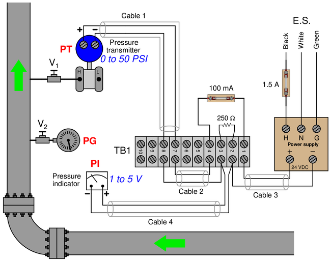
This pressure-measurement system seems to have a problem. The pressure gauge (PG) indicates 30 PSI, but the pressure indicator (PI) reads less than 0 PSI (“pegged” fully down-scale). A voltmeter connected between terminals 7 and 8 registers 24 VDC:

Identify the likelihood of each specified fault for this circuit. Consider each fault one at a time (i.e. no coincidental faults), determining whether or not each fault could independently account for all measurements and symptoms in this circuit.
$$\begin{array} {|l|l|} \hline Fault & Possible & Impossible \\ \hline 250 ohm resistor~Failed~open & & \\ \hline 100~mA~fuse~blown & & \\ \hline 1.5~A~fuse~blown & & \\ \hline Cable 1~Failed~open & & \\ \hline Cable 3~Failed~open & & \\ \hline Cable 1~Failed~shorted & & \\ \hline Cable 4~Failed~shorted & & \\ \hline \end{array}$$
Reveal answer$$\begin{array} {|l|l|} \hline Fault & Possible & Impossible \\ \hline 250 ohm resistor~Failed~open & & \surd \\ \hline 100 mA~fuse~blown & & \surd \\ \hline 1.5~A~fuse~blown & & \surd \\ \hline Cable 1~Failed~open & \surd & \\ \hline Cable 3~Failed~open & & \surd \\ \hline Cable 1~Failed~shorted & & \surd \\ \hline Cable 4~Failed~shorted & \surd & \\ \hline \end{array}$$
-
Question 35
This pressure-measurement system seems to have a problem. The pressure gauge (PG) indicates 30 PSI, but the pressure indicator (PI) reads over 50 PSI (“pegged” fully up-scale). A voltmeter connected between terminals 4 and 2 registers 24 VDC:
Identify the likelihood of each specified fault for this circuit. Consider each fault one at a time (i.e. no coincidental faults), determining whether or not each fault could independently account for all measurements and symptoms in this circuit.
$$\begin{array} {|l|l|} \hline Fault & Possible & Impossible \\ \hline 250 ohm resistor~Failed~open & & \\ \hline 100 mA~fuse~blown & & \\ \hline 1.5~A~fuse~blown & & \\ \hline Cable 1~Failed~open & & \\ \hline Cable 4~Failed~open & & \\ \hline Cable 1~Failed~shorted & & \\ \hline Cable 4~Failed~shorted & & \\ \hline \end{array}$$
Reveal answer$$\begin{array} {|l|l|} \hline Fault & Possible & Impossible \\ \hline 250 ohm resistor~Failed~open & \surd & \\ \hline 100 mA~fuse~blown & & \surd \\ \hline 1.5~A~fuse~blown & & \surd \\ \hline Cable 1~Failed~open & & \surd \\ \hline Cable 4~Failed~open & & \surd \\ \hline Cable 1~Failed~shorted & \surd & \\ \hline Cable 4~Failed~shorted & & \surd \\ \hline \end{array}$$
-
Question 36
This pressure-measurement system seems to have a problem. The pressure gauge (PG) indicates 30 PSI, but the pressure indicator (PI) reads less than 0 PSI (“pegged” fully down-scale). A voltmeter connected between terminals 7 and 8 registers 0 VDC:

Identify the likelihood of each specified fault for this circuit. Consider each fault one at a time (i.e. no coincidental faults), determining whether or not each fault could independently account for all measurements and symptoms in this circuit.
$$\begin{array} {|l|l|} \hline Fault & Possible & Impossible \\ \hline 250 ohm resistor~Failed~open & & \\ \hline 100 mA~fuse~blown & & \\ \hline 1.5~A~fuse~blown & & \\ \hline Cable 1~Failed~open & & \\ \hline Cable 4~Failed~open & & \\ \hline Cable 1~Failed~shorted & & \\ \hline Cable 4~Failed~shorted & & \\ \hline \end{array}$$
Reveal answer$$\begin{array} {|l|l|} \hline Fault & Possible & Impossible \\ \hline 250 ohm resistor~Failed~open & & \surd \\ \hline 100~mA~fuse~blown & \surd & \\ \hline 1.5~A~fuse~blown & \surd & \\ \hline Cable 1~Failed~open & & \surd \\ \hline Cable 4~Failed~open & & \surd \\ \hline Cable 1~Failed~shorted & & \surd \\ \hline Cable 4~Failed~shorted & & \surd \\ \hline \end{array}$$
-
Question 37
This pictorial diagram shows the wiring connections for a simple pressure control loop, where a loop-powered 4-20 mA pressure transmitter sends a signal to a Honeywell controller, which in turn sends another 4-20 mA signal to a control valve:

If an operator informs you that the control valve refuses to open even in manual mode, what types and locations of electrical faults might you suspect? Are there any non-electrical faults which might also cause this to happen?
Reveal answerIf the valve will not open, it means either a mechanical failure is preventing upward motion of the valve stem, or something is preventing air pressure from reaching the valve actuator. Possible faults include either an open or a short in the cable between the I/P and the controller. A dead controller (failed output, or failed AC power supply to the controller) could cause this as well.
Possible non-electrical faults include failed air supply to the I/P, plugged air line between I/P and valve, and a shut block valve at the supply port of the I/P.
No fault in the transmitter (input) circuit would have any effect on the controller’s output in manual mode, since the valve control circuit is independent of the transmitter circuit.
-
Question 38
This pictorial diagram shows the wiring connections for a simple pressure control loop, where a loop-powered 4-20 mA pressure transmitter sends a signal to a Honeywell controller, which in turn sends another 4-20 mA signal to a control valve:

If an operator informs you that the pressure indicated by the Honeywell controller is above range (“pegged” full upscale, reading +110
Reveal answerIf the Honeywell controller is pegged upscale, it means the analog input is receiving too much voltage. A failed-open resistor would do this, as would any short-circuit bypassing the transmitter.
No fault in the valve (output) circuit would have any effect on the controller’s indication of pressure, since the valve control circuit is independent of the transmitter circuit.
-
Question 39
Suppose a voltmeter registers 0 volts between test points {\bf C} and {\bf F} in this series-parallel circuit:

Identify the likelihood of each specified fault for this circuit. Consider each fault one at a time (i.e. no coincidental faults), determining whether or not each fault could independently account for all measurements and symptoms in this circuit.
$$\begin{array} {|l|l|} \hline Fault & Possible & Impossible \\ \hline R_1~Failed~open & & \\ \hline R_2~Failed~open & & \\ \hline R_3~Failed~open & & \\ \hline R_1~Failed~shorted & & \\ \hline R_2~Failed~shorted & & \\ \hline R_3~Failed~shorted & & \\ \hline Voltage~source~dead & & \\ \hline \end{array}$$
Reveal answer$$\begin{array} {|l|l|} \hline Fault & Possible & Impossible \\ \hline R_1~Failed~open & & \surd \\ \hline R_2~Failed~open & & \surd \\ \hline R_3~Failed~open & \surd & \\ \hline R_1~Failed~shorted & \surd & \\ \hline R_2~Failed~shorted & \surd & \\ \hline R_3~Failed~shorted & & \surd \\ \hline Voltage~source~dead & \surd & \\ \hline \end{array}$$
-
Question 40
Suppose an ammeter inserted between test points {\bf E} and {\bf F} registers 4 mA in this series-parallel circuit:

Identify the likelihood of each specified fault for this circuit. Consider each fault one at a time (i.e. no coincidental faults), determining whether or not each fault could independently account for all measurements and symptoms in this circuit.
$$\begin{array} {|l|l|} \hline Fault & Possible & Impossible \\ \hline R_1~Failed~open & & \\ \hline R_2~Failed~open & & \\ \hline R_3~Failed~open & & \\ \hline R_1~Failed~shorted & & \\ \hline R_2~Failed~shorted & & \\ \hline R_3~Failed~shorted & & \\ \hline Current~source~dead & & \\ \hline \end{array}$$
Reveal answer$$\begin{array} {|l|l|} \hline Fault & Possible & Impossible \\ \hline R_1~Failed~open & & \surd \\ \hline R_2~Failed~open & \surd & \\ \hline R_3~Failed~open & & \surd \\ \hline R_1~Failed~shorted & & \surd \\ \hline R_2~Failed~shorted & & \surd \\ \hline R_3~Failed~shorted & & \surd \\ \hline Current~source~dead & & \surd \\ \hline \end{array}$$
-
Question 41
Suppose an ammeter inserted between test points {\bf B} and {\bf D} registers 0 mA in this series-parallel circuit:

Identify the likelihood of each specified fault for this circuit. Consider each fault one at a time (i.e. no coincidental faults), determining whether or not each fault could independently account for all measurements and symptoms in this circuit.
$$\begin{array} {|l|l|} \hline Fault & Possible & Impossible \\ \hline R_1~Failed~open & & \\ \hline R_2~Failed~open & & \\ \hline R_3~Failed~open & & \\ \hline R_1~Failed~shorted & & \\ \hline R_2~Failed~shorted & & \\ \hline R_3~Failed~shorted & & \\ \hline Current~source~dead & & \\ \hline \end{array}$$
Reveal answer$$\begin{array} {|l|l|} \hline Fault & Possible & Impossible \\ \hline R_1~Failed~open & \surd & \\ \hline R_2~Failed~open & & \surd \\ \hline R_3~Failed~open & & \surd \\ \hline R_1~Failed~shorted & & \surd \\ \hline R_2~Failed~shorted & & \surd \\ \hline R_3~Failed~shorted & & \surd \\ \hline Current~source~dead & \surd & \\ \hline \end{array}$$
-
Question 42
Suppose a voltmeter registers 0 volts between test points {\bf C} and {\bf D} in this series-parallel circuit:

Identify the likelihood of each specified fault for this circuit. Consider each fault one at a time (i.e. no coincidental faults), determining whether or not each fault could independently account for all measurements and symptoms in this circuit.
$$\begin{array} {|l|l|} \hline Fault & Possible & Impossible \\ \hline R_1~Failed~open & & \\ \hline R_2~Failed~open & & \\ \hline R_3~Failed~open & & \\ \hline R_1~Failed~shorted & & \\ \hline R_2~Failed~shorted & & \\ \hline R_3~Failed~shorted & & \\ \hline Current~source~dead & & \\ \hline \end{array}$$
Reveal answer$$\begin{array} {|l|l|} \hline Fault & Possible & Impossible \\ \hline R_1~Failed~open & \surd & \\ \hline R_2~Failed~open & & \surd \\ \hline R_3~Failed~open & & \surd \\ \hline R_1~Failed~shorted & & \surd \\ \hline R_2~Failed~shorted & \surd & \\ \hline R_3~Failed~shorted & \surd & \\ \hline Current~source~dead & \surd & \\ \hline \end{array}$$
-
Question 43
Suppose an ammeter inserted between test points {\bf E} and {\bf C} registers 6 mA in this series-parallel circuit:
Identify the likelihood of each specified fault for this circuit. Consider each fault one at a time (i.e. no coincidental faults), determining whether or not each fault could independently account for all measurements and symptoms in this circuit.
$$\begin{array} {|l|l|} \hline Fault & Possible & Impossible \\ \hline R_1~Failed~open & & \\ \hline R_2~Failed~open & & \\ \hline R_3~Failed~open & & \\ \hline R_1~Failed~shorted & & \\ \hline R_2~Failed~shorted & & \\ \hline R_3~Failed~shorted & & \\ \hline Current~source~dead & & \\ \hline \end{array}$$
Reveal answerThe 6 mA current emanating from the current source is supposed to split up into equal parts (3 mA) through resistors R_2 and R_3. The fact that we measure a full 6 mA in the E-C wire tells us the splitting is not happening as it should. Instead of splitting, we seem to have all the current passing through R_3 with none of it passing through R_2.
Only two faults could explain this occurring, and that is an open R_2 (preventing current through it) or a shorted R_3 (diverting all current away from R_2):
$$\begin{array} {|l|l|} \hline Fault & Possible & Impossible \\ \hline R_1~Failed~open & & \surd \\ \hline R_2~Failed~open & \surd & \\ \hline R_3~Failed~open & & \surd \\ \hline R_1~Failed~shorted & & \surd \\ \hline R_2~Failed~shorted & & \surd \\ \hline R_3~Failed~shorted & \surd & \\ \hline Current~source~dead & & \surd \\ \hline \end{array}$$
-
Question 44
Suppose a voltmeter registers 8 volts between test points {\bf A} and {\bf F} in this series-parallel circuit:

Identify the likelihood of each specified fault for this circuit. Consider each fault one at a time (i.e. no coincidental faults), determining whether or not each fault could independently account for all measurements and symptoms in this circuit.
$$\begin{array} {|l|l|} \hline Fault & Possible & Impossible \\ \hline R_1~Failed~open & & \\ \hline R_2~Failed~open & & \\ \hline R_3~Failed~open & & \\ \hline R_1~Failed~shorted & & \\ \hline R_2~Failed~shorted & & \\ \hline R_3~Failed~shorted & & \\ \hline Current~source~dead & & \\ \hline \end{array}$$
Reveal answer$$\begin{array} {|l|l|} \hline Fault & Possible & Impossible \\ \hline R_1~Failed~open & & \surd \\ \hline R_2~Failed~open & \surd & \\ \hline R_3~Failed~open & \surd & \\ \hline R_1~Failed~shorted & & \surd \\ \hline R_2~Failed~shorted & & \surd \\ \hline R_3~Failed~shorted & & \surd \\ \hline Current~source~dead & & \surd \\ \hline \end{array}$$
-
Question 45
Suppose an ammeter inserted between test point {\bf D} and the nearest lead of resistor R_2 registers 0 mA in this series-parallel circuit:

Identify the likelihood of each specified fault for this circuit. Consider each fault one at a time (i.e. no coincidental faults), determining whether or not each fault could independently account for all measurements and symptoms in this circuit.
$$\begin{array} {|l|l|} \hline Fault & Possible & Impossible \\ \hline R_1~Failed~open & & \\ \hline R_2~Failed~open & & \\ \hline R_3~Failed~open & & \\ \hline R_1~Failed~shorted & & \\ \hline R_2~Failed~shorted & & \\ \hline R_3~Failed~shorted & & \\ \hline Current~source~dead & & \\ \hline \end{array}$$
Reveal answer$$\begin{array} {|l|l|} \hline Fault & Possible & Impossible \\ \hline R_1~Failed~open & \surd & \\ \hline R_2~Failed~open & \surd & \\ \hline R_3~Failed~open & & \surd \\ \hline R_1~Failed~shorted & & \surd \\ \hline R_2~Failed~shorted & & \surd \\ \hline R_3~Failed~shorted & \surd & \\ \hline Current~source~dead & \surd & \\ \hline \end{array}$$
-
Question 46
Suppose an ammeter inserted between test point {\bf C} and the nearest lead of resistor R_3 registers 4 mA in this series-parallel circuit:

Identify the likelihood of each specified fault for this circuit. Consider each fault one at a time (i.e. no coincidental faults), determining whether or not each fault could independently account for all measurements and symptoms in this circuit.
$$\begin{array} {|l|l|} \hline Fault & Possible & Impossible \\ \hline R_1~Failed~open & & \\ \hline R_2~Failed~open & & \\ \hline R_3~Failed~open & & \\ \hline R_1~Failed~shorted & & \\ \hline R_2~Failed~shorted & & \\ \hline R_3~Failed~shorted & & \\ \hline Current~source~dead & & \\ \hline \end{array}$$
Reveal answer$$\begin{array} {|l|l|} \hline Fault & Possible & Impossible \\ \hline R_1~Failed~open & & \surd \\ \hline R_2~Failed~open & \surd & \\ \hline R_3~Failed~open & & \surd \\ \hline R_1~Failed~shorted & & \surd \\ \hline R_2~Failed~shorted & & \surd \\ \hline R_3~Failed~shorted & \surd & \\ \hline Current~source~dead & & \surd \\ \hline \end{array}$$
-
Question 47
Suppose an ammeter inserted between test point {\bf C} and the nearest lead of resistor R_1 registers 0 mA in this series-parallel circuit:

Identify the likelihood of each specified fault for this circuit. Consider each fault one at a time (i.e. no coincidental faults), determining whether or not each fault could independently account for all measurements and symptoms in this circuit.
$$\begin{array} {|l|l|} \hline Fault & Possible & Impossible \\ \hline R_1~Failed~open & & \\ \hline R_2~Failed~open & & \\ \hline R_3~Failed~open & & \\ \hline R_1~Failed~shorted & & \\ \hline R_2~Failed~shorted & & \\ \hline R_3~Failed~shorted & & \\ \hline Voltage~source~dead & & \\ \hline \end{array}$$
Reveal answer$$\begin{array} {|l|l|} \hline Fault & Possible & Impossible \\ \hline R_1~Failed~open & \surd & \\ \hline R_2~Failed~open & & \surd \\ \hline R_3~Failed~open & \surd & \\ \hline R_1~Failed~shorted & & \surd \\ \hline R_2~Failed~shorted & \surd & \\ \hline R_3~Failed~shorted & & \surd \\ \hline Voltage~source~dead & \surd & \\ \hline \end{array}$$
-
Question 48
Suppose a voltmeter registers 6 volts between test points {\bf E} and {\bf C} in this series-parallel circuit:

Identify the likelihood of each specified fault for this circuit. Consider each fault one at a time (i.e. no coincidental faults), determining whether or not each fault could independently account for all measurements and symptoms in this circuit.
$$\begin{array} {|l|l|} \hline Fault & Possible & Impossible \\ \hline R_1~Failed~open & & \\ \hline R_2~Failed~open & & \\ \hline R_3~Failed~open & & \\ \hline R_1~Failed~shorted & & \\ \hline R_2~Failed~shorted & & \\ \hline R_3~Failed~shorted & & \\ \hline Voltage~source~dead & & \\ \hline \end{array}$$
Reveal answer$$\begin{array} {|l|l|} \hline Fault & Possible & Impossible \\ \hline R_1~Failed~open & \surd & \\ \hline R_2~Failed~open & \surd & \\ \hline R_3~Failed~open & & \surd \\ \hline R_1~Failed~shorted & & \surd \\ \hline R_2~Failed~shorted & & \surd \\ \hline R_3~Failed~shorted & & \surd \\ \hline Voltage~source~dead & & \surd \\ \hline \end{array}$$
-
Question 49
Suppose an ammeter inserted between test points {\bf D} and {\bf B} registers 16 mA in this series-parallel circuit:

Identify the likelihood of each specified fault for this circuit. Consider each fault one at a time (i.e. no coincidental faults), determining whether or not each fault could independently account for all measurements and symptoms in this circuit.
$$\begin{array} {|l|l|} \hline Fault & Possible & Impossible \\ \hline R_1~Failed~open & & \\ \hline R_2~Failed~open & & \\ \hline R_3~Failed~open & & \\ \hline R_1~Failed~shorted & & \\ \hline R_2~Failed~shorted & & \\ \hline R_3~Failed~shorted & & \\ \hline Voltage~source~dead & & \\ \hline \end{array}$$
Reveal answer$$\begin{array} {|l|l|} \hline Fault & Possible & Impossible \\ \hline R_1~Failed~open & \surd & \\ \hline R_2~Failed~open & & \surd \\ \hline R_3~Failed~open & \surd & \\ \hline R_1~Failed~shorted & & \surd \\ \hline R_2~Failed~shorted & & \surd \\ \hline R_3~Failed~shorted & & \surd \\ \hline Voltage~source~dead & & \surd \\ \hline \end{array}$$
-
Question 50
Suppose a voltmeter registers 12 volts between test points {\bf C} and {\bf D} in this series-parallel circuit:

Identify the likelihood of each specified fault for this circuit. Consider each fault one at a time (i.e. no coincidental faults), determining whether or not each fault could independently account for all measurements and symptoms in this circuit.
$$\begin{array} {|l|l|} \hline Fault & Possible & Impossible \\ \hline R_1~Failed~open & & \\ \hline R_2~Failed~open & & \\ \hline R_3~Failed~open & & \\ \hline R_1~Failed~shorted & & \\ \hline R_2~Failed~shorted & & \\ \hline R_3~Failed~shorted & & \\ \hline Voltage~source~dead & & \\ \hline \end{array}$$
Reveal answer$$\begin{array} {|l|l|} \hline Fault & Possible & Impossible \\ \hline R_1~Failed~open & & \surd \\ \hline R_2~Failed~open & & \surd \\ \hline R_3~Failed~open & & \surd \\ \hline R_1~Failed~shorted & & \surd \\ \hline R_2~Failed~shorted & & \surd \\ \hline R_3~Failed~shorted & \surd & \\ \hline Voltage~source~dead & & \surd \\ \hline \end{array}$$
-
Question 51
Suppose a voltmeter registers 6 volts between test points {\bf C} and {\bf B} in this series-parallel circuit:

Identify the likelihood of each specified fault for this circuit. Consider each fault one at a time (i.e. no coincidental faults), determining whether or not each fault could independently account for all measurements and symptoms in this circuit.
$$\begin{array} {|l|l|} \hline Fault & Possible & Impossible \\ \hline R_1~Failed~open & & \\ \hline R_2~Failed~open & & \\ \hline R_3~Failed~open & & \\ \hline R_1~Failed~shorted & & \\ \hline R_2~Failed~shorted & & \\ \hline R_3~Failed~shorted & & \\ \hline Voltage~source~dead & & \\ \hline \end{array}$$
Reveal answer$$\begin{array} {|l|l|} \hline Fault & Possible & Impossible \\ \hline R_1~Failed~open & \surd & \\ \hline R_2~Failed~open & \surd & \\ \hline R_3~Failed~open & & \surd \\ \hline R_1~Failed~shorted & & \surd \\ \hline R_2~Failed~shorted & & \surd \\ \hline R_3~Failed~shorted & & \surd \\ \hline Voltage~source~dead & & \surd \\ \hline \end{array}$$
-
Question 52
Suppose a voltmeter registers 18 volts between test points {\bf E} and {\bf C} while the pushbutton is released (not pressed), and 0 volts between test points {\bf A} and {\bf B} while the pushbutton is pressed:

Identify the likelihood of each specified fault for this circuit. Consider each fault one at a time (i.e. no coincidental faults), determining whether or not each fault could independently account for all measurements and symptoms in this circuit.
$$\begin{array} {|l|l|} \hline Fault & Possible & Impossible \\ \hline Switch~Failed~open & & \\ \hline R_1~Failed~open & & \\ \hline R_2~Failed~open & & \\ \hline R_3~Failed~open & & \\ \hline Switch~Failed~shorted & & \\ \hline R_1~Failed~shorted & & \\ \hline R_2~Failed~shorted & & \\ \hline R_3~Failed~shorted & & \\ \hline Voltage~source~dead & & \\ \hline \end{array}$$
Reveal answer$$\begin{array} {|l|l|} \hline Fault & Possible & Impossible \\ \hline Switch~Failed~open & \surd & \\ \hline R_1~Failed~open & & \surd \\ \hline R_2~Failed~open & & \surd \\ \hline R_3~Failed~open & & \surd \\ \hline Switch~Failed~shorted & & \surd \\ \hline R_1~Failed~shorted & \surd & \\ \hline R_2~Failed~shorted & & \surd \\ \hline R_3~Failed~shorted & & \surd \\ \hline Voltage~source~dead & & \surd \\ \hline \end{array}$$
-
Question 53
Suppose a voltmeter registers 0 volts between test points {\bf E} and {\bf C} while the pushbutton is released (not pressed), and 0 volts between test points {\bf B} and {\bf D} while the pushbutton is pressed:
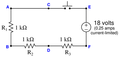
Identify the likelihood of each specified fault for this circuit. Consider each fault one at a time (i.e. no coincidental faults), determining whether or not each fault could independently account for all measurements and symptoms in this circuit.
$$\begin{array} {|l|l|} \hline Fault & Possible & Impossible \\ \hline Switch~Failed~open & & \\ \hline R_1~Failed~open & & \\ \hline R_2~Failed~open & & \\ \hline R_3~Failed~open & & \\ \hline Switch~Failed~shorted & & \\ \hline R_1~Failed~shorted & & \\ \hline R_2~Failed~shorted & & \\ \hline R_3~Failed~shorted & & \\ \hline Voltage~source~dead & & \\ \hline \end{array}$$
Reveal answer$$\begin{array} {|l|l|} \hline Fault & Possible & Impossible \\ \hline Switch~Failed~open & & \surd \\ \hline R_1~Failed~open & \surd & \\ \hline R_2~Failed~open & & \surd \\ \hline R_3~Failed~open & \surd & \\ \hline Switch~Failed~shorted & & \surd \\ \hline R_1~Failed~shorted & & \surd \\ \hline R_2~Failed~shorted & & \surd \\ \hline R_3~Failed~shorted & & \surd \\ \hline Voltage~source~dead & \surd & \\ \hline \end{array}$$
-
Question 54
Suppose the lamp refuses to light up when the pushbutton switch is pressed. A voltmeter registers 12 volts between test points {\bf C} and {\bf E} in the circuit while the pushbutton is released (not pressed):

Identify the likelihood of each specified fault for this circuit. Consider each fault one at a time (i.e. no coincidental faults), determining whether or not each fault could independently account for all measurements and symptoms in this circuit.
$$\begin{array} {|l|l|} \hline Fault & Possible & Impossible \\ \hline Open~wire~between~A~and~C & & \\ \hline Open~wire~between~B~and~D & & \\ \hline Open~wire~between~D~and~F & & \\ \hline Lamp~Failed~open & & \\ \hline Switch~Failed~open & & \\ \hline Lamp~Failed~shorted & & \\ \hline Switch~Failed~shorted & & \\ \hline Voltage~source~dead & & \\ \hline \end{array}$$
Reveal answer$$\begin{array} {|l|l|} \hline Fault & Possible & Impossible \\ \hline Open~wire~between~A~and~C & & \surd \\ \hline Open~wire~between~B~and~D & & \surd \\ \hline Open~wire~between~D~and~F & & \surd \\ \hline Lamp~Failed~open & & \surd \\ \hline Switch~Failed~open & \surd & \\ \hline Lamp~Failed~shorted & \surd & \\ \hline Switch~Failed~shorted & & \surd \\ \hline Voltage~source~dead & & \surd \\ \hline \end{array}$$
-
Question 55
Suppose the lamp refuses to light up when the pushbutton switch is pressed. A voltmeter registers 0 volts between test points {\bf E} and {\bf D} in the circuit while the pushbutton is pressed:

Identify the likelihood of each specified fault for this circuit. Consider each fault one at a time (i.e. no coincidental faults), determining whether or not each fault could independently account for all measurements and symptoms in this circuit.
$$\begin{array} {|l|l|} \hline Fault & Possible & Impossible \\ \hline Open~wire~between~A~and~C & & \\ \hline Open~wire~between~B~and~D & & \\ \hline Open~wire~between~D~and~F & & \\ \hline Lamp~Failed~open & & \\ \hline Switch~Failed~open & & \\ \hline Lamp~Failed~shorted & & \\ \hline Switch~Failed~shorted & & \\ \hline Voltage~source~dead & & \\ \hline \end{array}$$
Reveal answer$$\begin{array} {|l|l|} \hline Fault & Possible & Impossible \\ \hline Open~wire~between~A~and~C & & \surd \\ \hline Open~wire~between~B~and~D & & \surd \\ \hline Open~wire~between~D~and~F & \surd & \\ \hline Lamp~Failed~open & & \surd \\ \hline Switch~Failed~open & & \surd \\ \hline Lamp~Failed~shorted & \surd & \\ \hline Switch~Failed~shorted & & \surd \\ \hline Voltage~source~dead & \surd & \\ \hline \end{array}$$
-
Question 56
Suppose the lamp refuses to light up when the pushbutton switch is pressed. A voltmeter registers 0 volts between test points {\bf A} and {\bf D} in the circuit while the pushbutton is pressed:

Identify the likelihood of each specified fault for this circuit. Consider each fault one at a time (i.e. no coincidental faults), determining whether or not each fault could independently account for all measurements and symptoms in this circuit.
$$\begin{array} {|l|l|} \hline Fault & Possible & Impossible \\ \hline Open~wire~between~A~and~C & & \\ \hline Open~wire~between~B~and~D & & \\ \hline Open~wire~between~D~and~F & & \\ \hline Lamp~Failed~open & & \\ \hline Switch~Failed~open & & \\ \hline Lamp~Failed~shorted & & \\ \hline Switch~Failed~shorted & & \\ \hline Voltage~source~dead & & \\ \hline \end{array}$$
Reveal answer$$\begin{array} {|l|l|} \hline Fault & Possible & Impossible \\ \hline Open~wire~between~A~and~C & \surd & \\ \hline Open~wire~between~B~and~D & & \surd \\ \hline Open~wire~between~D~and~F & \surd & \\ \hline Lamp~Failed~open & & \surd \\ \hline Switch~Failed~open & \surd & \\ \hline Lamp~Failed~shorted & \surd & \\ \hline Switch~Failed~shorted & & \surd \\ \hline Voltage~source~dead & \surd & \\ \hline \end{array}$$
-
Question 57
Identify which of these are true statements:
{1.} Between two points that are electrically common to each other, there is guaranteed to be zero (or nearly zero) voltage.
{2.} If zero voltage is measured between two points, those points must be electrically common to each other.
{3.} Between two points that are not electrically common to each other, there is guaranteed to be voltage.
{4.} If voltage is measured between two points, those points cannot be electrically common to each other.
Reveal answerOnly two out of the four given statements are true:
{1.} Between two points that are electrically common to each other, there is guaranteed to be zero (or nearly zero) voltage.
{4.} If voltage is measured between two points, those points cannot be electrically common to each other.The fundamental concept of logic being applied here may be seen by examining the following statements—representing the same logical pattern of electrical statements given at the beginning of this question:
{1.} All rabbits are mammals.
{2.} All mammals are rabbits.
{3.} All non-rabbits are non-mammals.
{4.} All non-mammals are non-rabbits.Clearly, only statements 1 and 4 are true.
Notes:What we have here is an exercise in Aristotelian logic. In either scenario (points in a circuit, or animals), statement 2 is the {\it converse} of statement 1, while statement 3 is the {\it inverse} and statement 4 is the {\it contrapositive}. Only the contrapositive of a statement is guaranteed to share the same truth value as the original statement.
This is no esoteric exercise. Rather, it is a hard-learned fact: many students mistakenly think that because there is guaranteed to be no voltage between electrically common points in a circuit, then the absence of voltage between two points must mean those two points are electrically common to each other! This is not necessarily true, because situations exist where two points may not be electrically common, yet still have no voltage between them. Electrical commonality is just {\it one way} that two points can have zero voltage between them, not the only way!
The contrapositive of this rule, however, is a valuable troubleshooting tool: if there is substantial voltage measured between two points in a circuit, then we know without a doubt that those two points are {\it not} electrically common to each other!
-
Question 58
Suppose a voltmeter registers 4 volts between test points {\bf E} and {\bf C} in this series-parallel circuit:

Identify the likelihood of each specified fault for this circuit. Consider each fault one at a time (i.e. no coincidental faults), determining whether or not each fault could independently account for all measurements and symptoms in this circuit.
$$\begin{array} {|l|l|} \hline Fault & Possible & Impossible \\ \hline R_1~Failed~open & & \\ \hline R_2~Failed~open & & \\ \hline R_3~Failed~open & & \\ \hline R_1~Failed~shorted & & \\ \hline R_2~Failed~shorted & & \\ \hline R_3~Failed~shorted & & \\ \hline Current~source~dead & & \\ \hline \end{array}$$
Reveal answer$$\begin{array} {|l|l|} \hline Fault & Possible & Impossible \\ \hline R_1~Failed~open & & \surd \\ \hline R_2~Failed~open & & \surd \\ \hline R_3~Failed~open & & \surd \\ \hline R_1~Failed~shorted & \surd & \\ \hline R_2~Failed~shorted & \surd & \\ \hline R_3~Failed~shorted & & \surd \\ \hline Current~source~dead & & \surd \\ \hline \end{array}$$
-
Question 59
Suppose a voltmeter registers 12 volts between test points {\bf D} and {\bf A} in this series-parallel circuit:
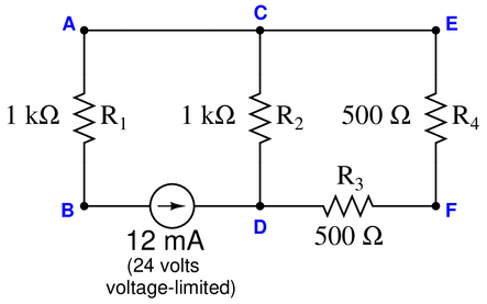
Identify the likelihood of each specified fault for this circuit. Consider each fault one at a time (i.e. no coincidental faults), determining whether or not each fault could independently account for all measurements and symptoms in this circuit.
$$\begin{array} {|l|l|} \hline Fault & Possible & Impossible \\ \hline R_1~Failed~open & & \\ \hline R_2~Failed~open & & \\ \hline R_3~Failed~open & & \\ \hline R_4~Failed~open & & \\ \hline R_1~Failed~shorted & & \\ \hline R_2~Failed~shorted & & \\ \hline R_3~Failed~shorted & & \\ \hline R_4~Failed~shorted & & \\ \hline Current~source~dead & & \\ \hline \end{array}$$
Reveal answer$$\begin{array} {|l|l|} \hline Fault & Possible & Impossible \\ \hline R_1~Failed~open & & \surd \\ \hline R_2~Failed~open & \surd & \\ \hline R_3~Failed~open & \surd & \\ \hline R_4~Failed~open & \surd & \\ \hline R_1~Failed~shorted & & \surd \\ \hline R_2~Failed~shorted & & \surd \\ \hline R_3~Failed~shorted & & \surd \\ \hline R_4~Failed~shorted & & \surd \\ \hline Current~source~dead & & \surd \\ \hline \end{array}$$
-
Question 60
Suppose a voltmeter registers 13.33 volts between test points {\bf D} and {\bf E} in this series-parallel circuit:

Identify the likelihood of each specified fault for this circuit. Consider each fault one at a time (i.e. no coincidental faults), determining whether or not each fault could independently account for all measurements and symptoms in this circuit.
$$\begin{array} {|l|l|} \hline Fault & Possible & Impossible \\ \hline R_1~Failed~open & & \\ \hline R_2~Failed~open & & \\ \hline R_3~Failed~open & & \\ \hline R_4~Failed~open & & \\ \hline R_1~Failed~shorted & & \\ \hline R_2~Failed~shorted & & \\ \hline R_3~Failed~shorted & & \\ \hline R_4~Failed~shorted & & \\ \hline Voltage~source~dead & & \\ \hline \end{array}$$
Reveal answer$$\begin{array} {|l|l|} \hline Fault & Possible & Impossible \\ \hline R_1~Failed~open & \surd & \\ \hline R_2~Failed~open & \surd & \\ \hline R_3~Failed~open & & \surd \\ \hline R_4~Failed~open & & \surd \\ \hline R_1~Failed~shorted & & \surd \\ \hline R_2~Failed~shorted & & \surd \\ \hline R_3~Failed~shorted & \surd & \\ \hline R_4~Failed~shorted & \surd & \\ \hline Voltage~source~dead & & \surd \\ \hline \end{array}$$
-
Question 61
Suppose a voltmeter registers 12 volts between test points {\bf A} and {\bf D} in this series-parallel circuit:

Identify the likelihood of each specified fault for this circuit. Consider each fault one at a time (i.e. no coincidental faults), determining whether or not each fault could independently account for all measurements and symptoms in this circuit.
$$\begin{array} {|l|l|} \hline Fault & Possible & Impossible \\ \hline R_1~Failed~open & & \\ \hline R_2~Failed~open & & \\ \hline R_3~Failed~open & & \\ \hline R_4~Failed~open & & \\ \hline R_1~Failed~shorted & & \\ \hline R_2~Failed~shorted & & \\ \hline R_3~Failed~shorted & & \\ \hline R_4~Failed~shorted & & \\ \hline Voltage~source~dead & & \\ \hline \end{array}$$
Reveal answer$$\begin{array} {|l|l|} \hline Fault & Possible & Impossible \\ \hline R_1~Failed~open & \surd & \\ \hline R_2~Failed~open & & \surd \\ \hline R_3~Failed~open & & \surd \\ \hline R_4~Failed~open & & \surd \\ \hline R_1~Failed~shorted & & \surd \\ \hline R_2~Failed~shorted & \surd & \\ \hline R_3~Failed~shorted & & \surd \\ \hline R_4~Failed~shorted & & \surd \\ \hline Voltage~source~dead & & \surd \\ \hline \end{array}$$
-
Question 62
Suppose a voltmeter registers 6 volts between test points {\bf D} and {\bf E} in this series-parallel circuit:

Identify the likelihood of each specified fault for this circuit. Consider each fault one at a time (i.e. no coincidental faults), determining whether or not each fault could independently account for all measurements and symptoms in this circuit.
$$\begin{array} {|l|l|} \hline Fault & Possible & Impossible \\ \hline R_1~Failed~open & & \\ \hline R_2~Failed~open & & \\ \hline R_3~Failed~open & & \\ \hline R_4~Failed~open & & \\ \hline R_1~Failed~shorted & & \\ \hline R_2~Failed~shorted & & \\ \hline R_3~Failed~shorted & & \\ \hline R_4~Failed~shorted & & \\ \hline Voltage~source~dead & & \\ \hline \end{array}$$
Reveal answer$$\begin{array} {|l|l|} \hline Fault & Possible & Impossible \\ \hline R_1~Failed~open & & \surd \\ \hline R_2~Failed~open & \surd & \\ \hline R_3~Failed~open & \surd & \\ \hline R_4~Failed~open & \surd & \\ \hline R_1~Failed~shorted & & \surd \\ \hline R_2~Failed~shorted & & \surd \\ \hline R_3~Failed~shorted & & \surd \\ \hline R_4~Failed~shorted & & \surd \\ \hline Voltage~source~dead & & \surd \\ \hline \end{array}$$
-
Question 63
Suppose a voltmeter registers 0 volts between test points {\bf F} and {\bf E} in this series-parallel circuit:

Identify the likelihood of each specified fault for this circuit. Consider each fault one at a time (i.e. no coincidental faults), determining whether or not each fault could independently account for all measurements and symptoms in this circuit.
$$\begin{array} {|l|l|} \hline Fault & Possible & Impossible \\ \hline R_1~Failed~open & & \\ \hline R_2~Failed~open & & \\ \hline R_3~Failed~open & & \\ \hline R_4~Failed~open & & \\ \hline R_1~Failed~shorted & & \\ \hline R_2~Failed~shorted & & \\ \hline R_3~Failed~shorted & & \\ \hline R_4~Failed~shorted & & \\ \hline Voltage~source~dead & & \\ \hline \end{array}$$
Reveal answer$$\begin{array} {|l|l|} \hline Fault & Possible & Impossible \\ \hline R_1~Failed~open & & \surd \\ \hline R_2~Failed~open & & \surd \\ \hline R_3~Failed~open & \surd & \\ \hline R_4~Failed~open & & \surd \\ \hline R_1~Failed~shorted & & \surd \\ \hline R_2~Failed~shorted & & \surd \\ \hline R_3~Failed~shorted & & \surd \\ \hline R_4~Failed~shorted & \surd & \\ \hline Voltage~source~dead & \surd & \\ \hline \end{array}$$
-
Question 64
Suppose a voltmeter registers 20 volts between test points {\bf D} and {\bf E} in this series-parallel circuit:

Identify the likelihood of each specified fault for this circuit. Consider each fault one at a time (i.e. no coincidental faults), determining whether or not each fault could independently account for all measurements and symptoms in this circuit.
$$\begin{array} {|l|l|} \hline Fault & Possible & Impossible \\ \hline R_1~Failed~open & & \\ \hline R_2~Failed~open & & \\ \hline R_3~Failed~open & & \\ \hline R_4~Failed~open & & \\ \hline R_1~Failed~shorted & & \\ \hline R_2~Failed~shorted & & \\ \hline R_3~Failed~shorted & & \\ \hline R_4~Failed~shorted & & \\ \hline Voltage~source~dead & & \\ \hline \end{array}$$
Reveal answer$$\begin{array} {|l|l|} \hline Fault & Possible & Impossible \\ \hline R_1~Failed~open & & \surd \\ \hline R_2~Failed~open & & \surd \\ \hline R_3~Failed~open & \surd & \\ \hline R_4~Failed~open & \surd & \\ \hline R_1~Failed~shorted & \surd & \\ \hline R_2~Failed~shorted & \surd & \\ \hline R_3~Failed~shorted & & \surd \\ \hline R_4~Failed~shorted & & \surd \\ \hline Voltage~source~dead & & \surd \\ \hline \end{array}$$
-
Question 65
Suppose a voltmeter registers 0 volts between test points {\bf A} and {\bf D} in this series-parallel circuit:

Identify the likelihood of each specified fault for this circuit. Consider each fault one at a time (i.e. no coincidental faults), determining whether or not each fault could independently account for all measurements and symptoms in this circuit.
$$\begin{array} {|l|l|} \hline Fault & Possible & Impossible \\ \hline R_1~Failed~open & & \\ \hline R_2~Failed~open & & \\ \hline R_3~Failed~open & & \\ \hline R_4~Failed~open & & \\ \hline R_1~Failed~shorted & & \\ \hline R_2~Failed~shorted & & \\ \hline R_3~Failed~shorted & & \\ \hline R_4~Failed~shorted & & \\ \hline Voltage~source~dead & & \\ \hline \end{array}$$
Reveal answer$$\begin{array} {|l|l|} \hline Fault & Possible & Impossible \\ \hline R_1~Failed~open & & \surd \\ \hline R_2~Failed~open & & \surd \\ \hline R_3~Failed~open & \surd & \\ \hline R_4~Failed~open & \surd & \\ \hline R_1~Failed~shorted & \surd & \\ \hline R_2~Failed~shorted & \surd & \\ \hline R_3~Failed~shorted & & \surd \\ \hline R_4~Failed~shorted & & \surd \\ \hline Voltage~source~dead & \surd & \\ \hline \end{array}$$
-
Question 66
Suppose an ammeter inserted between test point {\bf F} and the nearest lead of resistor R_3 registers 0 mA in this series-parallel circuit:

Identify the likelihood of each specified fault for this circuit. Consider each fault one at a time (i.e. no coincidental faults), determining whether or not each fault could independently account for all measurements and symptoms in this circuit.
$$\begin{array} {|l|l|} \hline Fault & Possible & Impossible \\ \hline R_1~Failed~open & & \\ \hline R_2~Failed~open & & \\ \hline R_3~Failed~open & & \\ \hline R_1~Failed~shorted & & \\ \hline R_2~Failed~shorted & & \\ \hline R_3~Failed~shorted & & \\ \hline Current~source~dead & & \\ \hline \end{array}$$
Reveal answer$$\begin{array} {|l|l|} \hline Fault & Possible & Impossible \\ \hline R_1~Failed~open & \surd & \\ \hline R_2~Failed~open & & \surd \\ \hline R_3~Failed~open & \surd & \\ \hline R_1~Failed~shorted & & \surd \\ \hline R_2~Failed~shorted & \surd & \\ \hline R_3~Failed~shorted & & \surd \\ \hline Current~source~dead & \surd & \\ \hline \end{array}$$
-
Question 67
Everything I know about troubleshooting, I learned from Tyler Durden (with respects to the movie {\it Fight Club}):
{The Rules of \underline{ Fault Club}}
(1) Don’t try to find the fault by looking for it—perform diagnostic tests instead
(2) {\it Don't try to find the fault by looking for it -- perform diagnostic tests instead!}
(3) The troubleshooting is over when you have correctly identified the nature and location of the fault
(4) It’s just you and the fault—don’t ask for help until you have exhausted your resources
(5) Assume one fault at a time in a proven system, unless the data proves otherwise
(6) No new components allowed—replacing suspected bad components with new is a waste of time and money
(7) We will practice as many times as we have to until you master this
(8) Troubleshooting is not a spectator sport:
For each of these rules, explain their rationale.
Reveal answer{\bf Rules 1 and 2:} A very bad tendency of novice troubleshooters is to waste time visually looking for that which cannot be seen. Most faults in a system are difficult if not impossible to visually spot. Instead, the proficient troubleshooter always relies on test data and logical reasoning to identify the fault, all the way to the very end.
{\bf Rule 3:} Novice troubleshooters tend to stop prematurely. If you cannot pinpoint the exact nature and location of the fault, either you do not know enough about the subsystem you’re trying to diagnose, or you need to continue troubleshooting.
{\bf Rule 4:} Novice troubleshooters tend to ask for others’ help prematurely. You are not going to build this vital skill unless and until you are forced to do the thinking on your own!
{\bf Rule 5:} This is nothing more than {\it Occam's Razor} applied to diagnostics. Single faults are generally more probable than coincidental faults, especially on previously-working systems.
{\bf Rule 6:} Incompetent troubleshooters simply replace all the components they can find until the problem goes away. This is incredibly wasteful, and worse yet does nothing to develop skill.
{\bf Rule 7:} Practice makes perfect. Troubleshooting is a difficult skill to master, and it takes lots of time to develop.
{\bf Rule 8:} Never fool yourself by thinking you have learned something complex just because you have watched someone else do it! Unless and until you have done something yourself, {\it you don't know it.}
Notes:{\bf Original rules from the movie "Fight Club"}
{(1)} You do not talk about Fight Club
{(2)} {\it You do not talk about Fight Club}
{(3)} If someone yells “Stop,” goes limp, taps out, the fight is over
{(4)} Only two guys to a fight
{(5)} One fight at a time
{(6)} No shirts, no shoes
{(7)} Fights will go on as long as they have to
{(8)} If this is your first night at Fight Club, you have to fight!
-
Question 68
Suppose a voltmeter registers 0 volts between test points {\bf C} and {\bf E} in this series-parallel circuit:

Identify the likelihood of each specified fault for this circuit. Consider each fault one at a time (i.e. no coincidental faults), determining whether or not each fault could independently account for all measurements and symptoms in this circuit.
$$\begin{array} {|l|l|} \hline Fault & Possible & Impossible \\ \hline R_1~Failed~open & & \\ \hline R_2~Failed~open & & \\ \hline R_3~Failed~open & & \\ \hline R_1~Failed~shorted & & \\ \hline R_2~Failed~shorted & & \\ \hline R_3~Failed~shorted & & \\ \hline Current~source~dead & & \\ \hline \end{array}$$
Reveal answer0 volts between C and E means either no current through that resistor, or it’s shorted and cannot drop a voltage.
$$\begin{array} {|l|l|} \hline Fault & Possible & Impossible \\ \hline R_1~Failed~open & & \surd \\ \hline R_2~Failed~open & & \surd \\ \hline R_3~Failed~open & \surd & \\ \hline R_1~Failed~shorted & \surd & \\ \hline R_2~Failed~shorted & \surd & \\ \hline R_3~Failed~shorted & & \surd \\ \hline Current~source~dead & \surd & \\ \hline \end{array}$$
-
Question 69
Suppose a voltmeter registers 4 volts between test points {\bf A} and {\bf C} in this series-parallel circuit:
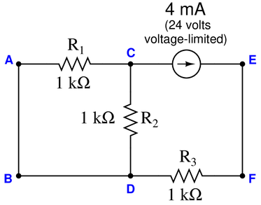
Identify the likelihood of each specified fault for this circuit. Consider each fault one at a time (i.e. no coincidental faults), determining whether or not each fault could independently account for all measurements and symptoms in this circuit.
$$\begin{array} {|l|l|} \hline Fault & Possible & Impossible \\ \hline R_1~Failed~open & & \\ \hline R_2~Failed~open & & \\ \hline R_3~Failed~open & & \\ \hline R_1~Failed~shorted & & \\ \hline R_2~Failed~shorted & & \\ \hline R_3~Failed~shorted & & \\ \hline Current~source~dead & & \\ \hline \end{array}$$
Reveal answer$$\begin{array} {|l|l|} \hline Fault & Possible & Impossible \\ \hline R_1~Failed~open & & \surd \\ \hline R_2~Failed~open & \surd & \\ \hline R_3~Failed~open & & \surd \\ \hline R_1~Failed~shorted & & \surd \\ \hline R_2~Failed~shorted & & \surd \\ \hline R_3~Failed~shorted & & \surd \\ \hline Current~source~dead & & \surd \\ \hline \end{array}$$
-
Question 70
Suppose a voltmeter registers 24 volts between test points {\bf C} and {\bf A} in this series-parallel circuit:

Identify the likelihood of each specified fault for this circuit. Consider each fault one at a time (i.e. no coincidental faults), determining whether or not each fault could independently account for all measurements and symptoms in this circuit.
$$\begin{array} {|l|l|} \hline Fault & Possible & Impossible \\ \hline R_1~Failed~open & & \\ \hline R_2~Failed~open & & \\ \hline R_3~Failed~open & & \\ \hline R_1~Failed~shorted & & \\ \hline R_2~Failed~shorted & & \\ \hline R_3~Failed~shorted & & \\ \hline Current~source~dead & & \\ \hline \end{array}$$
Reveal answer$$\begin{array} {|l|l|} \hline Fault & Possible & Impossible \\ \hline R_1~Failed~open & \surd & \\ \hline R_2~Failed~open & & \surd \\ \hline R_3~Failed~open & & \surd \\ \hline R_1~Failed~shorted & & \surd \\ \hline R_2~Failed~shorted & & \surd \\ \hline R_3~Failed~shorted & & \surd \\ \hline Current~source~dead & & \surd \\ \hline \end{array}$$
-
Question 71
Suppose a voltmeter registers 0 volts between test points {\bf D} and {\bf B} in this series-parallel circuit:

Identify the likelihood of each specified fault for this circuit. Consider each fault one at a time (i.e. no coincidental faults), determining whether or not each fault could independently account for all measurements and symptoms in this circuit.
$$\begin{array} {|l|l|} \hline Fault & Possible & Impossible \\ \hline R_1~Failed~open & & \\ \hline R_2~Failed~open & & \\ \hline R_3~Failed~open & & \\ \hline R_1~Failed~shorted & & \\ \hline R_2~Failed~shorted & & \\ \hline R_3~Failed~shorted & & \\ \hline Voltage~source~dead & & \\ \hline \end{array}$$
Reveal answer$$\begin{array} {|l|l|} \hline Fault & Possible & Impossible \\ \hline R_1~Failed~open & & \surd \\ \hline R_2~Failed~open & & \surd \\ \hline R_3~Failed~open & \surd & \\ \hline R_1~Failed~shorted & \surd & \\ \hline R_2~Failed~shorted & \surd & \\ \hline R_3~Failed~shorted & & \surd \\ \hline Voltage~source~dead & \surd & \\ \hline \end{array}$$
-
Question 72
Suppose a voltmeter registers 18 volts between test points {\bf C} and {\bf E} in this series-parallel circuit:

Identify the likelihood of each specified fault for this circuit. Consider each fault one at a time (i.e. no coincidental faults), determining whether or not each fault could independently account for all measurements and symptoms in this circuit.
$$\begin{array} {|l|l|} \hline Fault & Possible & Impossible \\ \hline R_1~Failed~open & & \\ \hline R_2~Failed~open & & \\ \hline R_3~Failed~open & & \\ \hline R_1~Failed~shorted & & \\ \hline R_2~Failed~shorted & & \\ \hline R_3~Failed~shorted & & \\ \hline Voltage~source~dead & & \\ \hline \end{array}$$
Reveal answer$$\begin{array} {|l|l|} \hline Fault & Possible & Impossible \\ \hline R_1~Failed~open & & \surd \\ \hline R_2~Failed~open & & \surd \\ \hline R_3~Failed~open & \surd & \\ \hline R_1~Failed~shorted & \surd & \\ \hline R_2~Failed~shorted & \surd & \\ \hline R_3~Failed~shorted & & \surd \\ \hline Voltage~source~dead & & \surd \\ \hline \end{array}$$
-
Question 73
Suppose an ammeter inserted between test point {\bf D} and the nearest lead of voltage source registers 9 mA in this series-parallel circuit:

Identify the likelihood of each specified fault for this circuit. Consider each fault one at a time (i.e. no coincidental faults), determining whether or not each fault could independently account for all measurements and symptoms in this circuit.
$$\begin{array} {|l|l|} \hline Fault & Possible & Impossible \\ \hline R_1~Failed~open & & \\ \hline R_2~Failed~open & & \\ \hline R_3~Failed~open & & \\ \hline R_1~Failed~shorted & & \\ \hline R_2~Failed~shorted & & \\ \hline R_3~Failed~shorted & & \\ \hline Voltage~source~dead & & \\ \hline \end{array}$$
Reveal answer$$\begin{array} {|l|l|} \hline Fault & Possible & Impossible \\ \hline R_1~Failed~open & \surd & \\ \hline R_2~Failed~open & \surd & \\ \hline R_3~Failed~open & & \surd \\ \hline R_1~Failed~shorted & & \surd \\ \hline R_2~Failed~shorted & & \surd \\ \hline R_3~Failed~shorted & & \surd \\ \hline Voltage~source~dead & & \surd \\ \hline \end{array}$$
-
Question 74
Suppose an ammeter inserted between test point {\bf C} and the nearest lead of resistor R_2 registers 9 mA in this series-parallel circuit:
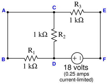
Identify the likelihood of each specified fault for this circuit. Consider each fault one at a time (i.e. no coincidental faults), determining whether or not each fault could independently account for all measurements and symptoms in this circuit.
$$\begin{array} {|l|l|} \hline Fault & Possible & Impossible \\ \hline R_1~Failed~open & & \\ \hline R_2~Failed~open & & \\ \hline R_3~Failed~open & & \\ \hline R_1~Failed~shorted & & \\ \hline R_2~Failed~shorted & & \\ \hline R_3~Failed~shorted & & \\ \hline Voltage~source~dead & & \\ \hline \end{array}$$
Reveal answer$$\begin{array} {|l|l|} \hline Fault & Possible & Impossible \\ \hline R_1~Failed~open & \surd & \\ \hline R_2~Failed~open & & \surd \\ \hline R_3~Failed~open & & \surd \\ \hline R_1~Failed~shorted & & \surd \\ \hline R_2~Failed~shorted & & \surd \\ \hline R_3~Failed~shorted & & \surd \\ \hline Voltage~source~dead & & \surd \\ \hline \end{array}$$
-
Question 75
Suppose a voltmeter registers 16 volts between test points {\bf F} and {\bf D} in this series-parallel circuit:

Identify the likelihood of each specified fault for this circuit. Consider each fault one at a time (i.e. no coincidental faults), determining whether or not each fault could independently account for all measurements and symptoms in this circuit.
$$\begin{array} {|l|l|} \hline Fault & Possible & Impossible \\ \hline R_1~Failed~open & & \\ \hline R_2~Failed~open & & \\ \hline R_3~Failed~open & & \\ \hline R_1~Failed~shorted & & \\ \hline R_2~Failed~shorted & & \\ \hline R_3~Failed~shorted & & \\ \hline Voltage~source~dead & & \\ \hline \end{array}$$
Reveal answer$$\begin{array} {|l|l|} \hline Fault & Possible & Impossible \\ \hline R_1~Failed~open & \surd & \\ \hline R_2~Failed~open & & \surd \\ \hline R_3~Failed~open & & \surd \\ \hline R_1~Failed~shorted & & \surd \\ \hline R_2~Failed~shorted & & \surd \\ \hline R_3~Failed~shorted & \surd & \\ \hline Voltage~source~dead & & \surd \\ \hline \end{array}$$