Facebook
 Google
 GitHub
 Linkedin
Electricity and Electronics
Pictorial Circuit Diagrams
-
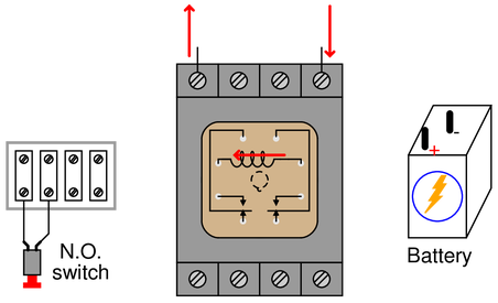
Question 1
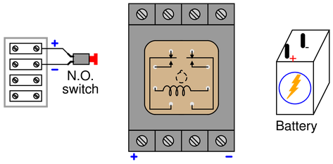
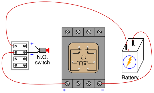
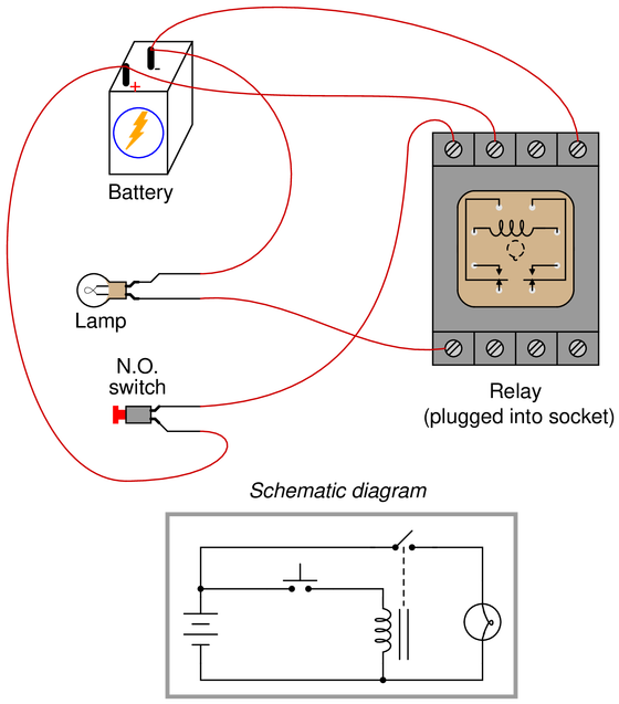
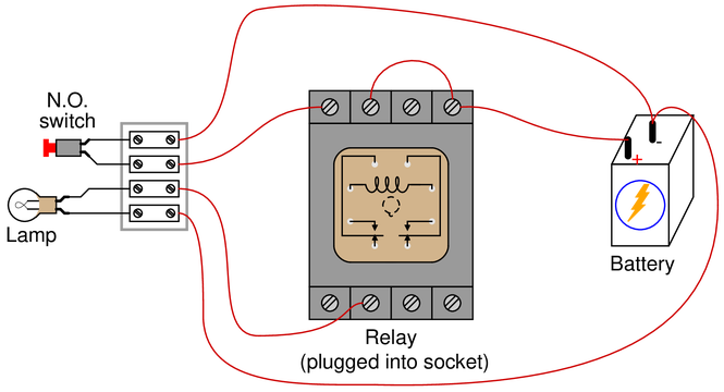
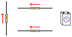
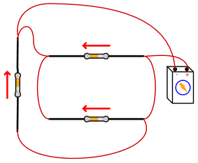
Sketch connecting wires such that the relay will energize when the normally-open (NO) pushbutton switch is pressed. Be sure to wire the relay in such a way that voltage will appear in the polarities shown by the (+) and (-) marks:
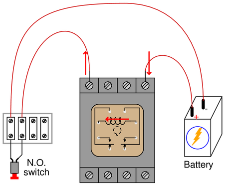
 Reveal answer
Bear in mind that this is not the only possible circuit solution:
Challenge yourself by designing a different circuit to meet the same criteria!
——————
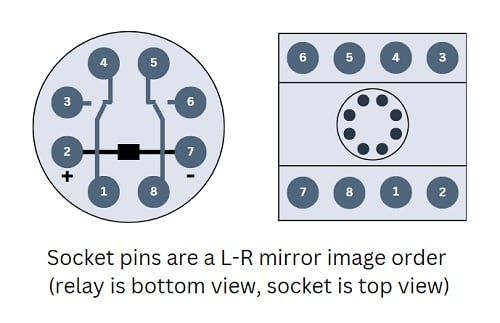
Use this wiring diagram to translate between the relay terminals and screws on the socket base.
 Notes:
This is called ‘power side switching’ because the switching device is connected between the load and the power supply (+) terminal.
Try to re-wire for ‘ground side switching’ - Read more here! -
Question 2
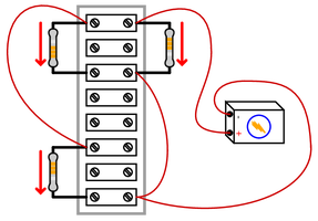
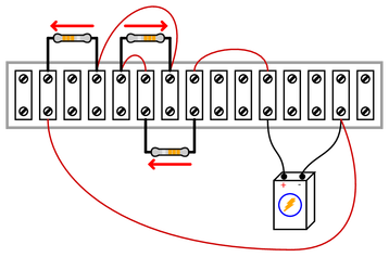
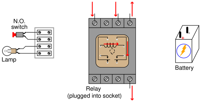
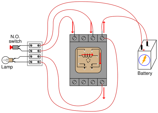
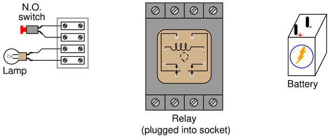
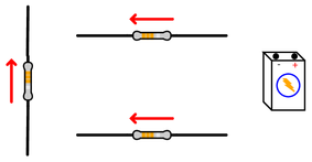
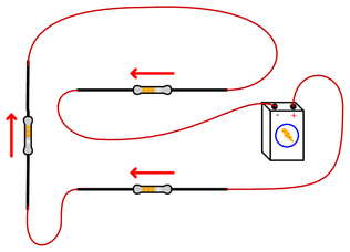
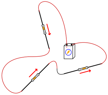
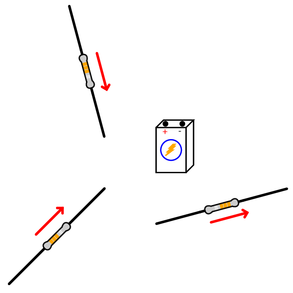
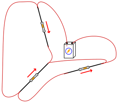
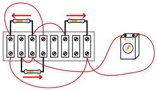
Sketch connecting wires such that the relay will energize when the normally-open (NO) pushbutton switch is pressed. Be sure to wire the relay in such a way that current (conventional flow) follows the directions indicated by the arrows:
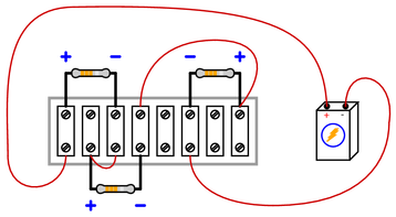
 Reveal answer
Bear in mind that this is not the only possible circuit solution:
Challenge yourself by designing a different circuit to meet the same criteria!
——————
Use this wiring diagram to translate between the relay terminals and screws on the socket base.
Note that this relay is rotated from the previous question.
Notes:This is called ‘ground side switching’ because the switching device is connected between the load and the power supply (-) terminal.
Try to re-wire for ‘power side switching’ - Read more here! -
Question 3
Sketch connecting wires such that the relay will energize and turn on the lamp when the normally-open (NO) pushbutton switch is pressed. Use the following schematic diagram as a guide:
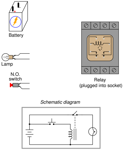
Note how the relay coil and lamp are separate (parallel) branches in this circuit. The pushbutton switch only carries the coil current, while the relay’s switch contact only carries the lamp current.
{\bullet} Suppose the battery is rated at 12 volts, the lamp has a resistance of 3.2 ohms when energized, and the relay coil has a wire resistance of 240 ohms. Calculate the amount of current carried by the switch when it is pressed.
Reveal answerBear in mind that this is not the only possible circuit solution:
Challenge yourself by designing a different circuit to meet the same criteria!
Regarding the current calculation, a close look at this circuit reveals it to be a parallel combination of the relay coil and the lamp as the two loads. The two switches provide negligible resistance, so we can solve this as a simple parallel circuit:
$$I_{total}=I_{coil}+I_{lamp}$$
$$I_{coil}={V_{battery} \over R{coil}}$$
$$I_{lamp}={V_{battery} \over R{lamp}}$$
——————
Notes:Note how a schematic diagram was provided for you, to help you determine where each and every wire should go. In real-life situations, you may not be given any schematic diagram at all. In such cases, it is an excellent problem-solving strategy to first sketch your own schematic diagram, before attempting to sketch a pictorial diagram or connect real wires to the devices. The concept here is that schematic diagrams are much easier to interpret and understand than pictorial diagrams where wires tend to cross over each other more, and where components are not always optimally placed.
-
Question 4
Sketch connecting wires such that the relay will energize and turn on the lamp when the normally-open (NO) pushbutton switch is pressed. Be sure to wire the relay in such a way that current (conventional flow) follows the directions indicated by the arrows, and that the switch only carries relay coil current (no lamp current in addition to coil current):
 Reveal answer
Bear in mind that this is not the only possible circuit solution:
Challenge yourself by designing a different circuit to meet the same criteria!
——————
-
Question 5
Sketch connecting wires such that the relay will energize and turn the lamp off when the normally-open (NO) pushbutton switch is pressed (i.e. the lamp should be on only when the pushbutton switch is not being pressed).
Be sure to wire the relay in such a way that the switch only carries relay coil current (no lamp current in addition to coil current):
 Reveal answer
Bear in mind that this is not the only possible circuit solution:
Challenge yourself by designing a different circuit to meet the same criteria!
——————
-
Question 6
Sketch connecting wires such that the relay will select one of two different thermocouples to send millivoltage signals to a temperature indicator. Use the following schematic diagram as a guide:
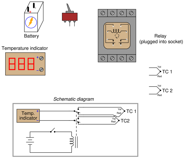 Reveal answer
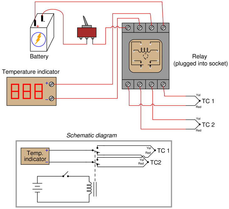
This kind of circuit is common when two sources must be toggled to a single destination. It is also used to reverse the polarity of DC motors.
The load device is connected to the relay’s common (COM) terminals. One source is connected to the NO terminals, while the other source is connected to the NC terminals, the sources being TC1/TC2 in this circuit.
——————
Notes:Note how a schematic diagram was provided for you, to help you determine where each and every wire should go. In real-life situations, you may not be given any schematic diagram at all. In such cases, it is an excellent problem-solving strategy to first sketch your own schematic diagram, before attempting to sketch a pictorial diagram or connect real wires to the devices. The concept here is that schematic diagrams are much easier to interpret and understand than pictorial diagrams where wires tend to cross over each other more, and where components are not always optimally placed.
-
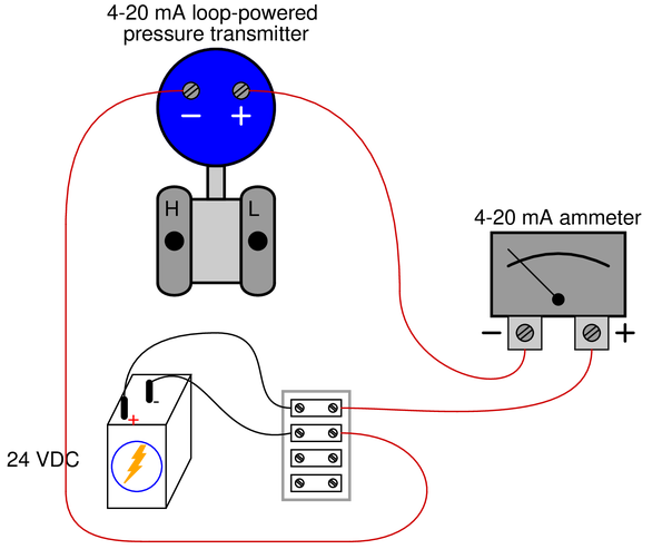
Question 7
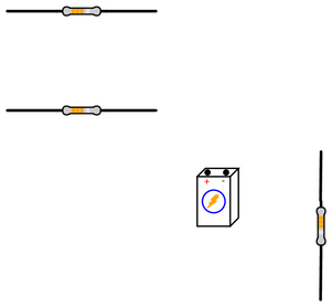
Draw connecting wires that will create a {\it series} circuit, such that the loop-powered pressure transmitter will drive the ammeter to indicate pressure:
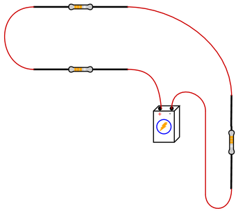
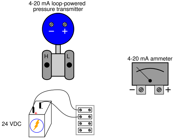 Reveal answer
Bear in mind that this is not the only possible circuit solution:
Challenge yourself by designing a different circuit that will also work!
-
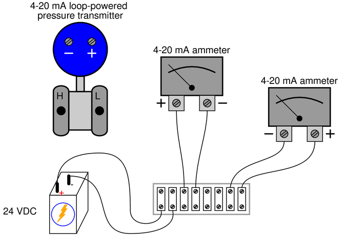
Question 8
Draw connecting wires that will create a {\it series} circuit, such that the loop-powered pressure transmitter will drive both ammeters to indicate pressure:
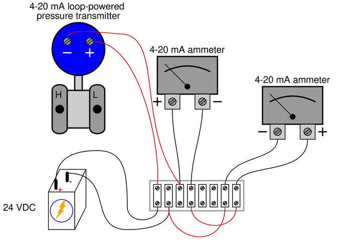
 Reveal answer
Bear in mind that this is not the only possible circuit solution:
Challenge yourself by designing a different circuit that will also work!
-
Question 9
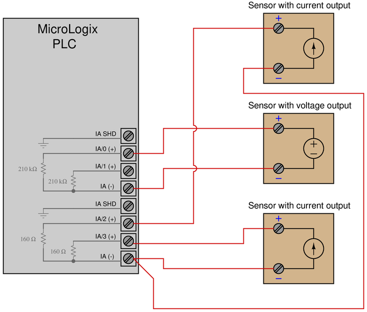
Some models of the “MicroLogix” series of programmable logic controller (PLC) manufactured by Allen-Bradley come equipped with analog inputs, designed to receive either voltage or current signals from analog sensors. Examine the internal resistances of the analog inputs (IA/0, IA/1, IA/2, and IA/3) to determine which are designed to input voltage signals and which are designed to input current signals.
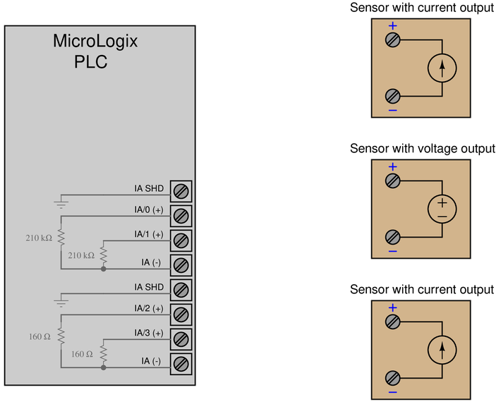
Hint: think in terms of the input resistances of voltmeters and ammeters. Which of these test instrument types are known for having very large input resistance values? Which of these test instrument types are known for having very small input resistance values?
Assuming the three sensors shown all have internal power sources (no need for an external DC power supply to make them output their respective signals), draw connecting wires between these sensors and the appropriate inputs on the PLC.
Reveal answerIA/0 and IA/1 are both analog voltage inputs. We know this because of their large input resistances (210 kΩ).
IA/2 and IA/3 are both analog current inputs. We know this because of their small input resistances (160 Ω).
-
Question 10
Draw connecting wires between the 4-20 mA loop-powered pressure transmitter, the 24 VDC power supply, and the “PV input” of the Honeywell controller so that the controller registers the measured pressure as its process variable (PV):
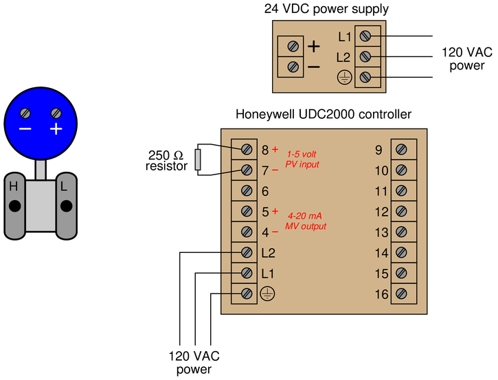 Reveal answer
Bear in mind that this is not the only possible circuit solution:
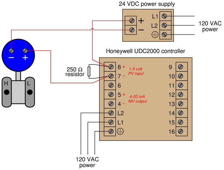
Challenge yourself by designing a different circuit to meet the same criteria!
-
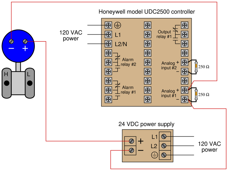
Question 11
Draw connecting wires between the 4-20 mA loop-powered pressure transmitter, the 24 VDC power supply, and “Analog input #1” of the Honeywell UDC2500 controller so that the controller registers the measured pressure as its process variable (PV):
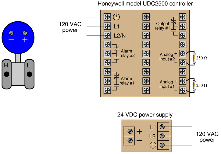 Reveal answer
Bear in mind that this is not the only possible circuit solution:
Challenge yourself by designing a different circuit to meet the same criteria!
-
Question 12
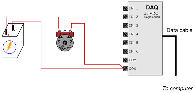
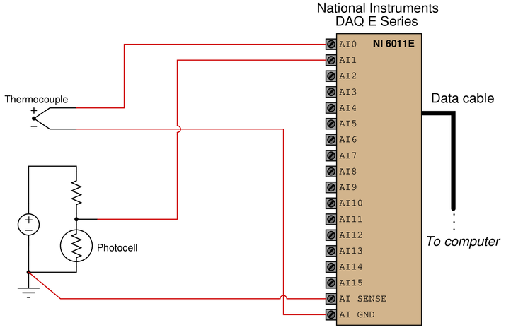
Sketch connecting wires to allow this data acquisition unit (DAQ) to sense the voltage produced by the solar cell, on input channel #2:
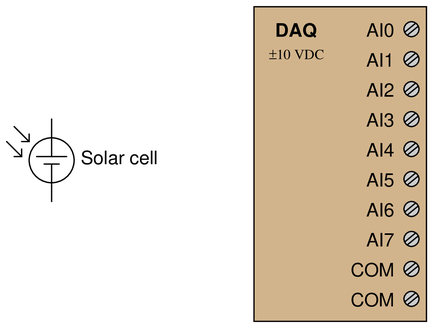
Your circuit should be wired in such a way that greater light intensity falling on the cell produces a more positive signal measured by the DAQ.
Reveal answer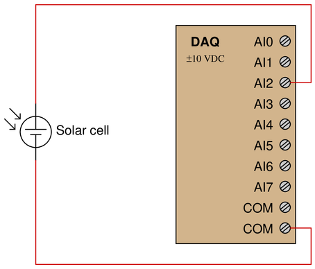
Challenge yourself by designing a different circuit to meet the same criteria!
-
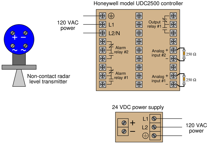
Question 13
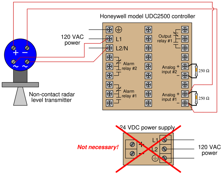
Draw connecting wires between the 4-20 mA self-powered (4-wire) level transmitter, the 24 VDC power supply, and “Analog input #1” of the Honeywell UDC2500 controller so that the controller registers the measured level as its process variable (PV). Assume the 4-wire transmitter’s analog output is the sourcing type:
 Reveal answer
This is a bit of a trick question, because there is no need for the 24 VDC power supply. The self-powered (4-wire) level transmitter functions as a current source rather than a current regulator as would be the case if it were loop-powered (2-wire).
-
Question 14
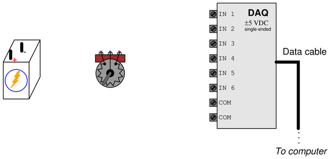
Sketch connecting wires so that this DAQ unit will register an increasing positive voltage on channel 2 as the potentiometer shaft is turned clockwise:
-
Question 15
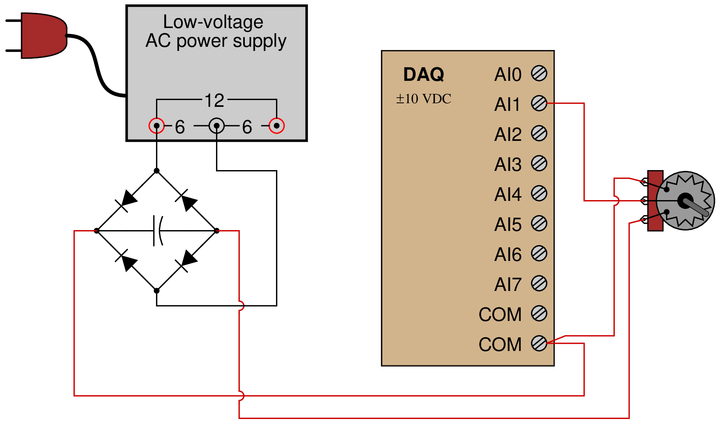
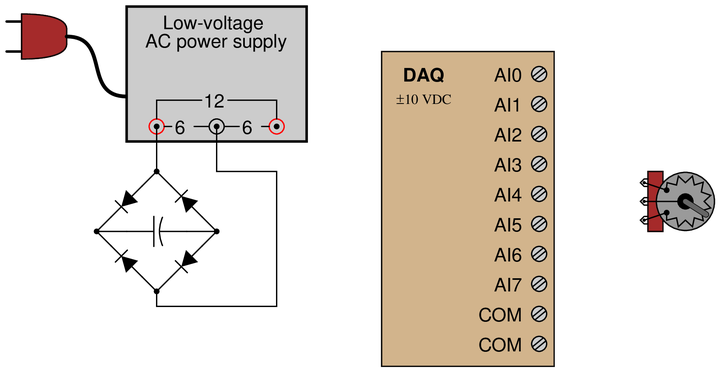
Sketch connecting wires so that this DAQ unit will register an increasing positive voltage on channel 5 as the potentiometer wiper moves to the left:
-
Question 16
Sketch connecting wires so that this DAQ unit will register an increasing negative voltage on channel 1 as the potentiometer shaft is turned clockwise:
-
Question 17
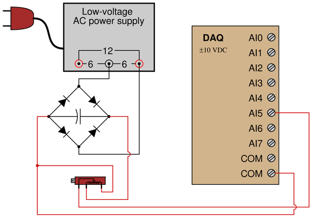
Determine how to connect this DAQ unit to measure the output voltage of the Wheatstone bridge in such a way that an increasing compression on the strain gauge causes a positive indication at channel 3 of the DAQ, and that the same DAQ channel will register zero when the strain gauge is at rest:
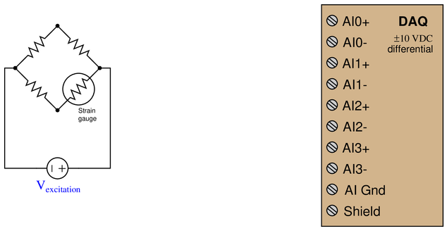 Reveal answer
Remember that stretching a strain gauge causes its resistance to increase, while compressing a strain gauge causes its resistance to decrease:
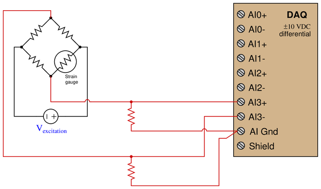
The two resistors (typically high-value, in the hundreds of kilo-ohms or even mega-ohms) provide a path for the DAQ’s input bias currents, which is essential for a differential-input amplifier such as the instrumentation amplifier circuits inside the DAQ.
-
Question 18
Sketch connecting wires to allow this data acquisition unit (DAQ) to sense strain using quarter-bridge strain gauge circuits on input channels #0 and #3, such that increasing tension on the strain gauge (increasing gauge resistance) generates a more positive signal voltage on each channel:
 Reveal answer
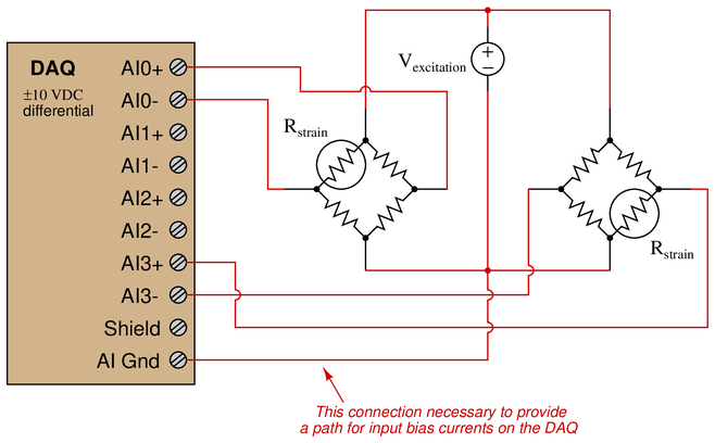
Challenge yourself by designing a different circuit to meet the same criteria!
-
Question 19
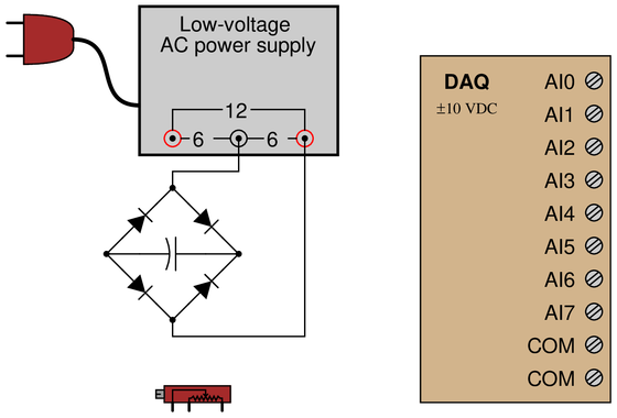
Suppose we wished to use this DAQ unit to measure the peak inverse voltage across diode $D_3$ during operation of the power supply circuit. Identify how we should connect channel 1 of the DAQ to do this, assuming we want the DAQ to register a positive value at the moment in time of the diode’s peak inverse voltage:
 Reveal answer
The phrase “peak inverse voltage” refers to the maximum instantaneous voltage impressed across a diode in the diode’s reverse-bias (blocking) direction. Thus, the peak we wish to capture will be positive on the cathode and negative on the anode:
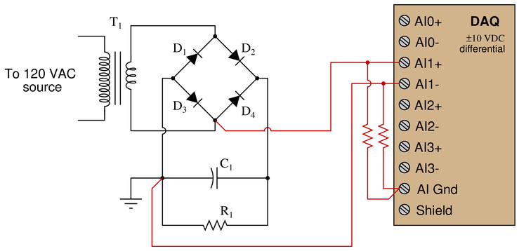
A simpler way to manage input bias currents on the DAQ is to simply connect one of the input terminals to the DAQ ground terminal like this (although doing so may yield results a bit less precise give the unequal bias current paths to ground):
-
Question 20
Identify suitable input terminals, proper modes, and necessary connecting wires to allow this National Instruments E-series data acquisition unit (DAQ) to sense the two voltage sources shown:

The available modes for the input channels are RSE, NRSE, and DIFF:
$$\begin{array} {|l|l|} \hline Channel & Mode & First terminal & Second terminal \\ \hline 0 & & & \\ \hline 1 & & & \\ \hline \end{array}$$
Reveal answerThis is one possible solution:
$$\begin{array} {|l|l|} \hline Channel & Mode & First terminal & Second terminal \\ \hline 0 & RSE & AI0 & AI Gnd \\ \hline 1 & NRSE & AI1 & AI Sense \\ \hline \end{array}$$
-
Question 21
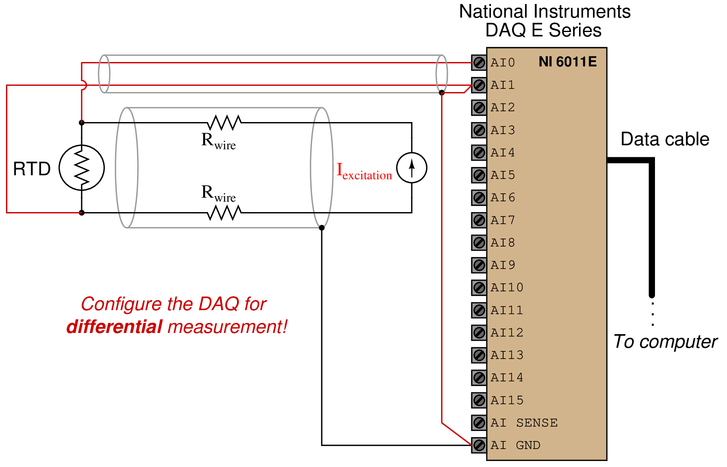
Here, a temperature sensor called an RTD is used to translate ambient temperature into a proportional resistance. This in turn is converted into a proportional voltage signal by a constant current fed through the RTD by the current source:
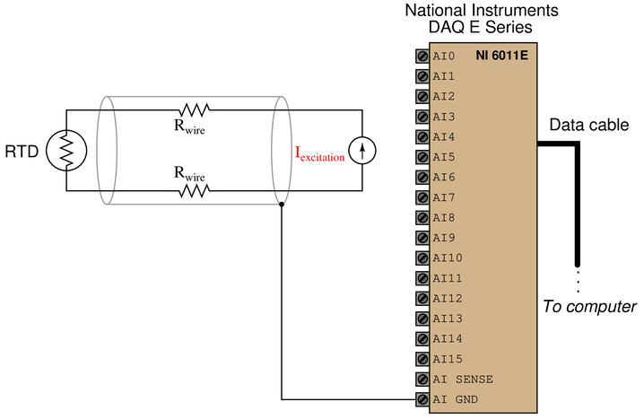
Determine how to connect the first analog input channel this DAQ to measure the RTD’s voltage drop, but in such a way that voltage dropped along the cable’s length will not affect the measurement. Also, determine whether this DAQ should be configured for single-ended or differential input
-
Question 22
Draw connecting wires to create a parallel circuit, such that voltage will drop across each resistor in the polarity shown by the (+) and (-) symbols:

{\bullet} Supposing the battery has a voltage of 1.5 volts, and all resistors are 1 kΩ in resistance value, calculate the voltage dropped by each resistor.
{\bullet} Supposing the battery has a voltage of 1.5 volts, and all resistors are 1 kΩ in resistance value, calculate the current passing through each resistor as well as the current passing through the battery.
Reveal answerBear in mind that this is not the only possible circuit solution:
Challenge yourself by designing a different circuit to meet the same criteria!
-
Question 23
Draw connecting wires that will create a parallel circuit with all the components shown:

{\bullet} Supposing the battery has a voltage of 6 volts, and all resistors are 1 kΩ in resistance value, calculate the voltage dropped by each resistor.
{\bullet} Supposing the battery has a voltage of 6 volts, and all resistors are 1 kΩ in resistance value, calculate the current passing through each resistor as well as the current passing through the battery.
Reveal answerBear in mind that this is not the only possible circuit solution!
Challenge yourself by designing a different circuit to meet the same criteria! -
Question 24
Draw connecting wires that will create a series circuit, such that current (conventional flow notation) will follow the directions shown by the arrows near each resistor:
{\bullet} Supposing the battery has a voltage of 12 volts, and all resistors are 1 kΩ in resistance value, calculate the voltage dropped by each resistor.
{\bullet} Supposing the battery has a voltage of 12 volts, and all resistors are 1 kΩ in resistance value, calculate the current passing through each resistor as well as the current passing through the battery.
Reveal answerBear in mind that this is not the {\it only} possible circuit solution:
Challenge yourself by designing a different circuit to meet the same criteria!
-
Question 25
Draw connecting wires that will create a parallel circuit, such that current (conventional flow notation) will follow the directions shown by the arrows near each resistor:
{\bullet} Supposing the battery has a voltage of 3 volts, and all resistors are 1 kΩ in resistance value, calculate the voltage dropped by each resistor.
{\bullet} Supposing the battery has a voltage of 3 volts, and all resistors are 1 kΩ in resistance value, calculate the current passing through each resistor as well as the current passing through the battery.
Reveal answerBear in mind that this is not the only possible circuit solution:
Challenge yourself by designing a different circuit to meet the same criteria!
-
Question 26
Draw connecting wires that will create a series circuit, such that current (conventional flow notation) will follow the directions shown by the arrows near each resistor:

{\bullet} Supposing the battery has a voltage of 4 volts, and all resistors are 1 kΩ in resistance value, calculate the voltage dropped by each resistor.
{\bullet} Supposing the battery has a voltage of 4 volts, and all resistors are 1 kΩ in resistance value, calculate the current passing through each resistor as well as the current passing through the battery.
Reveal answerBear in mind that this is not the only possible circuit solution:
Challenge yourself by designing a different circuit to meet the same criteria!
-
Question 27
Draw connecting wires that will create a parallel circuit, such that current (conventional flow notation) will follow the directions shown by the arrows near each resistor:
{\bullet} Supposing the battery has a voltage of 8 volts, and all resistors are 1 kΩ in resistance value, calculate the voltage dropped by each resistor.
{\bullet} Supposing the battery has a voltage of 8 volts, and all resistors are 1 kΩ in resistance value, calculate the current passing through each resistor as well as the current passing through the battery.
Reveal answerBear in mind that this is not the only possible circuit solution:
Challenge yourself by designing a different circuit to meet the same criteria!
-
Question 28
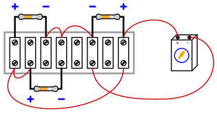
Draw connecting wires that will create a series circuit with the three resistors and battery:
{\bullet} Supposing the battery has a voltage of 15 volts, and all resistors are 1 kΩ in resistance value, calculate the voltage dropped by each resistor.
{\bullet} Supposing the battery has a voltage of 15 volts, and all resistors are 1 kΩ in resistance value, calculate the current passing through each resistor as well as the current passing through the battery.
Reveal answerBear in mind that this is not the only possible circuit solution:
Challenge yourself by designing a different circuit to meet the same criteria!
-
Question 29
Draw connecting wires that will create a parallel circuit with the three resistors and battery:

{\bullet} Supposing the battery has a voltage of 12 volts, and all resistors are 1 kΩ in resistance value, calculate the voltage dropped by each resistor.
{\bullet} Supposing the battery has a voltage of 12 volts, and all resistors are 1 kΩ in resistance value, calculate the current passing through each resistor as well as the current passing through the battery.
Reveal answerBear in mind that this is not the only possible circuit solution:
Challenge yourself by designing a different circuit to meet the same criteria!
-
Question 30
Draw connecting wires that will create a series circuit, such that current (conventional flow notation) will follow the directions shown by the arrows near each resistor:
{\bullet} Supposing the battery has a voltage of 10 volts, and all resistors are 1 kΩ in resistance value, calculate the voltage dropped by each resistor.
{\bullet} Supposing the battery has a voltage of 10 volts, and all resistors are 1 kΩ in resistance value, calculate the current passing through each resistor as well as the current passing through the battery.
Reveal answerBear in mind that this is not the only possible circuit solution:
Challenge yourself by designing a different circuit to meet the same criteria!
-
Question 31
Draw connecting wires that will create a parallel circuit, such that current (conventional flow notation) will follow the directions shown by the arrows near each resistor:

{\bullet} Supposing the battery has a voltage of 7 volts, and all resistors are 1 kΩ in resistance value, calculate the voltage dropped by each resistor.
{\bullet} Supposing the battery has a voltage of 7 volts, and all resistors are 1 kΩ in resistance value, calculate the current passing through each resistor as well as the current passing through the battery.
Reveal answerBear in mind that this is not the only possible circuit solution:
Challenge yourself by designing a different circuit to meet the same criteria!
-
Question 32
Draw connecting wires that will create a series circuit, such that voltage will drop across each resistor in the polarity shown by the (+) and (-) symbols:

{\bullet} Supposing the battery has a voltage of 1.5 volts, and all resistors are 1 kΩ in resistance value, calculate the voltage dropped by each resistor.
{\bullet} Supposing the battery has a voltage of 1.5 volts, and all resistors are 1 kΩ in resistance value, calculate the current passing through each resistor as well as the current passing through the battery.
Reveal answerBear in mind that this is not the only possible circuit solution:
Challenge yourself by designing a different circuit to meet the same criteria!
-
Question 33
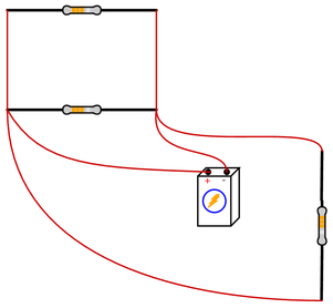
Draw connecting wires that will create a series circuit with all the components shown:
{\bullet} Supposing the battery has a voltage of 9 volts, and all resistors are 1 kΩ in resistance value, calculate the voltage dropped by each resistor.
{\bullet} Supposing the battery has a voltage of 9 volts, and all resistors are 1 kΩ in resistance value, calculate the current passing through each resistor as well as the current passing through the battery.
Reveal answerBear in mind that this is not the only possible circuit solution!
Challenge yourself by designing a different circuit to meet the same criteria! -
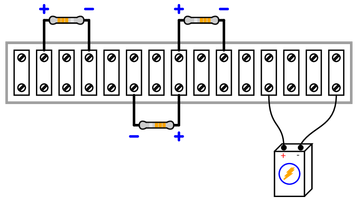
Question 34
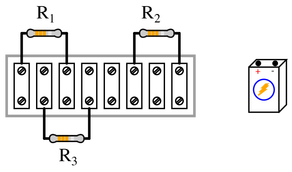
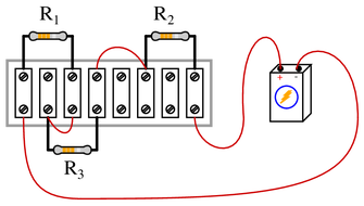
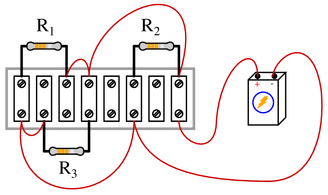
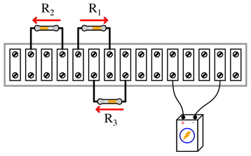
Resistors $R_1$ and $R_2$ are connected in parallel by virtue of being attached to the same two terminals on the terminal strip. Draw connecting wires that will create a series circuit between the parallel ${R_1 \over R_2$ pair and the lone resistor $R_3$, such that voltage will drop across each resistor in the polarity shown by the (+) and (-) symbols:
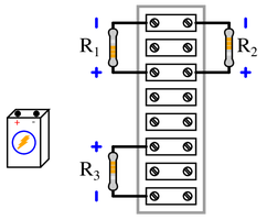
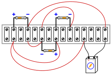
{\bullet} Supposing the battery has a voltage of 11 volts, and all resistors are 1 kΩ in resistance value, calculate the voltage dropped by each resistor.
{\bullet} Supposing the battery has a voltage of 11 volts, and all resistors are 1 kΩ in resistance value, calculate the current passing through each resistor as well as the current passing through the battery.
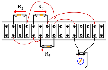
Reveal answerBear in mind that this is not the only possible circuit solution:
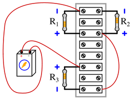
Challenge yourself by designing a different circuit to meet the same criteria!
-
Question 35
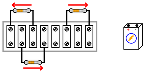
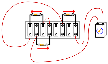
Draw connecting wires that will create a parallel circuit between all three resistors, such that current (conventional flow notation) will go through each resistor as shown by the arrows:
{\bullet} Supposing the battery has a voltage of 14 volts, and all resistors are 1 kΩ in resistance value, calculate the voltage dropped by each resistor.
{\bullet} Supposing the battery has a voltage of 14 volts, and all resistors are 1 kΩ in resistance value, calculate the current passing through each resistor as well as the current passing through the battery.
-
Question 36
Draw connecting wires that will create a series circuit between all three resistors, such that current (conventional flow notation) will go through each resistor as shown by the arrows:
{\bullet} Supposing the battery has a voltage of 18 volts, and all resistors are 1 kΩ in resistance value, calculate the voltage dropped by each resistor.
{\bullet} Supposing the battery has a voltage of 18 volts, and all resistors are 1 kΩ in resistance value, calculate the current passing through each resistor as well as the current passing through the battery.
-
Question 37
Draw connecting wires that will create a parallel circuit, such that voltage will drop across each resistor in the polarity shown by the (+) and (-) symbols:
{\bullet} Supposing the battery has a voltage of 2 volts, and all resistors are 1 kΩ in resistance value, calculate the voltage dropped by each resistor.
{\bullet} Supposing the battery has a voltage of 2 volts, and all resistors are 1 kΩ in resistance value, calculate the current passing through each resistor as well as the current passing through the battery.
Reveal answerBear in mind that this is not the {\it only} possible circuit solution:
Challenge yourself by designing a different circuit to meet the same criteria!
-
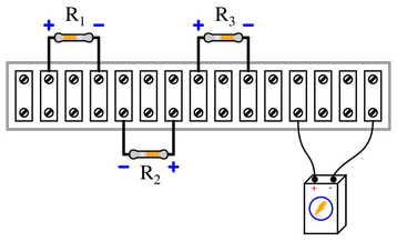
Question 38
Draw connecting wires that will create a series-parallel circuit, such that the voltage dropped across $R_1$ will be twice as much as the voltage dropped across $R_2$ or $R_3$. Make sure each resistor drops voltage in the polarity shown by the (+) and (-) symbols:
{\bullet} Supposing the battery has a voltage of 12 volts, and all resistors are 1 kΩ in resistance value, calculate the voltage dropped by each resistor.
{\bullet} Supposing the battery has a voltage of 12 volts, and all resistors are 1 kΩ in resistance value, calculate the current passing through each resistor as well as the current passing through the battery.
Reveal answerBear in mind that this is not the only possible circuit solution:
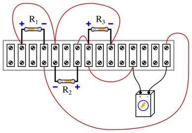
Challenge yourself by designing a different circuit to meet the same criteria!
-
Question 39
Draw connecting wires that will create a series-parallel circuit, such that the voltage dropped across $R_1$ will be twice as much as the voltage dropped across $R_2$ or $R_3$. Make sure each resistor passes current (conventional flow notation) in the directions as shown by the arrows:
{\bullet} Supposing the battery has a voltage of 18 volts, and all resistors are 1 kΩ in resistance value, calculate the voltage dropped by each resistor.
{\bullet} Supposing the battery has a voltage of 18 volts, and all resistors are 1 kΩ in resistance value, calculate the current passing through each resistor as well as the current passing through the battery.
Reveal answerBear in mind that this is not the only possible circuit solution:
Challenge yourself by designing a different circuit to meet the same criteria!
-
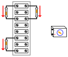
Question 40
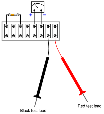
Suppose we needed to connect a resistor in series with a sensitive analog meter movement to range that meter for a certain maximum voltage, and we were going to make all connections using a terminal strip. Draw connecting wires that will create a series circuit between the meter and the resistor, such that polarity of the applied voltage will be correct for the meter with the red test lead being positive and the black test lead being negative:
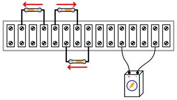
 Reveal answer
Bear in mind that this is not the only possible circuit solution:
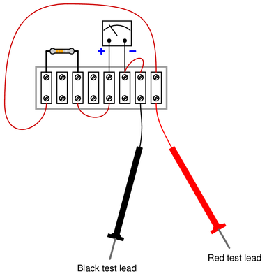
Challenge yourself by designing a different circuit to meet the same criteria!
-
Question 41
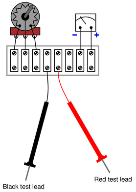
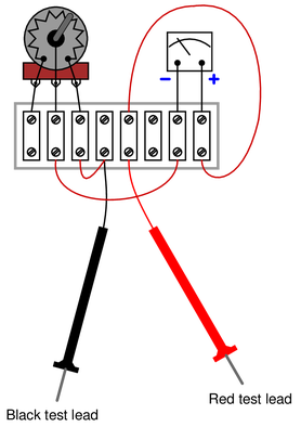
Suppose we needed to connect a variable resistor in series with a sensitive analog meter movement to range that meter for a certain maximum voltage, and we were going to make all connections using a terminal strip. Draw connecting wires that will create a series circuit between the meter and two terminals of the potentiometer, such that polarity of the applied voltage will be correct for the meter with the red test lead being positive and the black test lead being negative:
 Reveal answer
Bear in mind that this is not the only possible circuit solution:
Challenge yourself by designing a different circuit to meet the same criteria!
-
Question 42
Determine whether moving the potentiometer knob clockwise will increase or decrease the sensitivity of this analog voltmeter:
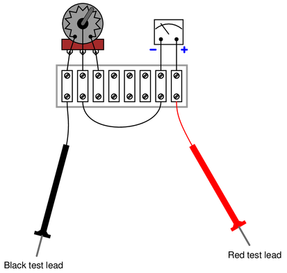
{\bullet} Which way would we need to turn the potentiometer in order to make the voltmeter have a higher range (i.e. full-scale deflection represents a greater measured voltage value than before)
Reveal answerTurning the knob clockwise will decrease the meter’s sensitivity (i.e. make the needle move less with the same amount of applied voltage at the test lead tips). This is due to the potentiometer’s resistance increasing between the left and center terminals as the wiper sweeps clockwise on the resistive strip.