Facebook
 Google
 GitHub
 Linkedin
Instrumentation and Process Control
RTD and Thermocouple Circuits
19 questions
-
Question 1 of 19
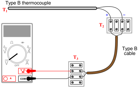
Calculate the amount of voltage “seen” by the voltmeter given the following measurement and reference junction temperatures:
{\bullet} $T_1 = 589~^{\circ}F$ ; $T_2 = 63~^{\circ}F$ ; $T_3 = 70~^{\circ}F$ ; $V_{meter} =$
{\bullet} $T_1 = 821~^{\circ}F$ ; $T_2 = 69~^{\circ}F$ ; $T_3 = 73~^{\circ}F$ ; $V_{meter} =$
{\bullet} $T_1 = 1524~^{\circ}F$ ; $T_2 = 91~^{\circ}F$ ; $T_3 = 105~^{\circ}F$ ; $V_{meter} =$
{\bullet} $T_1 = 1922~^{\circ}F$ ; $T_2 = 102~^{\circ}F$ ; $T_3 = 135~^{\circ}F$ ; $V_{meter} =$
Reveal answerAll answers based on ITS-90 thermocouple table values:
{\bullet} $T_1 = 589~^{\circ}F$ ; $T_2 = 63~^{\circ}F$ ; $T_3 = 70~^{\circ}F$ ; $V_{meter} = 0.463~mV$
{\bullet} $T_1 = 821~^{\circ}F$ ; $T_2 = 69~^{\circ}F$ ; $T_3 = 73~^{\circ}F$ ; $V_{meter} = 0.953~mV$
{\bullet} $T_1 = 1524~^{\circ}F$ ; $T_2 = 91~^{\circ}F$ ; $T_3 = 105~^{\circ}F$ ; $V_{meter} = 3.378~mV$
{\bullet} $T_1 = 1922~^{\circ}F$ ; $T_2 = 102~^{\circ}F$ ; $T_3 = 135~^{\circ}F$ ; $V_{meter} = 5.294~mV$
Note: all temperatures at $T_2$ are irrelevant because this is a junction between similar metals (type B wires connecting to corresponding type B wires). The reference (cold) junction is where the type B wires connect to copper, at temperature $T_3$.
Notes:
For all worksheet questions, temperature conversions and table lookups might be necessary.
For conversions, refer to Control Automation’s temperature conversion calculator and for table references, refer to the National Institute of Standards and Technology (NIST) website.
Reference educational links:
-
Question 2 of 19
This thermocouple is installed improperly:
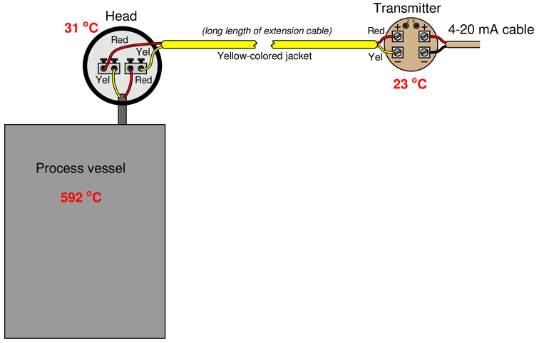
Identify the nature of the problem, and then calculate the millivoltage seen at the screw terminals of the temperature transmitter given the temperatures shown. After that, calculate the temperature interpreted by the transmitter assuming it has cold junction compensation (CJC) enabled.
Reveal answerThe extension wire has been connected “backwards” to the thermocouple. Yellow should connect to yellow, and red to red!
Seeing how the four junctions’ voltages interact is best done by drawing the circuit with each junction explicitly labeled as to polarity. You will see that the process and reference (transmitter) junctions are aiding each other, and the two junctions formed at the head are opposing the first two (but aiding each other). The formula for calculating voltage at the transmitter screw terminals then becomes:
$$V_{terminals} = V_{592^oC} + V_{23^oC} - V_{31^oC} - V_{31^oC}$$
$$V_{terminals} = 24.57~mV + 0.92~mV - 1.24~mV - 1.24~mV$$
$$V_{terminals} = 23.01~mV$$
If the transmitter has CJC enabled, it will add 0.92 mV to compensate for the reference junction, making the interpreted (measurement junction) voltage equal to 23.93 mV. This equates to 577 °C, which is substantially cooler than the real process temperature.
Notes:Reference educational links:
-
Question 3 of 19
Part of this solar-heating control system uses a dual-thermocouple circuit to compare the temperature inside the solar collector against the temperature inside the house, preventing the circulation fan from running if the house is ever warmer than the collector:
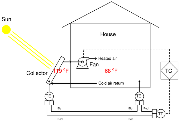
Answer the following questions about this subsystem:
{\bullet} Identify the thermocouple type used in this application, and determine whether or not this type is a good choice.
{\bullet} Calculate the voltage measured at the input terminals of the transmitter, and also determine whether or not this transmitter needs to be enabled for reference junction compensation.
{\bullet} Identify the meaning of the diamond-shaped PID symbol labeled “TC”.
Reveal answerThese are type ‘T’ thermocouples, sending 1.174 mV to the transmitter’s input. Cold junction compensation (CJC) should not be enabled in the transmitter, because we want to measure the difference in temperature between the collector and the house, not compensate for one of those thermocouples’ voltages!
The diamond symbol is a logic device—most likely a PLC—used for on/off control of the fan.
Notes:Reference educational links: