 Facebook
 Google
 GitHub
 Linkedin
Comparing Mechanical vs Hydraulic Forces
In honor of May the 4th, Star Wars Day, we compare the sources and applications of the two most common force-delivery systems - mechanical and hydraulic.
The definition of force is a fundamental stepping stone into any physics course. Force itself is the basic application of weight or strength, usually against a heavy load, with the intention of getting some useful task accomplished. If work is actually done, and the load is moved, this is called ‘work’. The amount of work, divided by the time it took to complete the work is called the ‘power’.
Obviously, without the initial presence of force, there would be no work done, and no conversion of energy resulting in the generation or use of power. And that would be a pretty boring world.
Industrial control systems are concerned with only one thing: accomplishing the task as accurately as possible with the least amount of waste. The motion of systems occurs in three main broad categories - those being mechanical, electrical, and fluid. Electrical control, however, is simply using electricity to move a mechanical device, so the final device responsible for force comes down to either the mechanical or fluid system.

Figure 1. Metal stamping (or pressing, or shearing) requires tremendous linear force from hydraulic or mechanical sources. Image used courtesy of Canva
Mechanical Forces
There are two kinds of motion - rotary and linear. No matter the situation, engineers have designed systems to deliver whatever motion is required.
Mechanical Rotation
In rotary motion, the motor is usually the go-to driver for force delivery. Motors are rated in HP or kW, both of which are a power rating, a combined effect of torque and rotational speed (rpm). If we wish to determine the amount of force delivered by a rotating object, the torque is the determining component.
Torque is a force applied at a distance from the center of rotation. If a motor can deliver a certain torque at a given RPM, a larger radial distance from the rotation would yield a smaller force delivery. To increase the force, you must either increase the RPM, or increase the HP of the motor and continue driving at the same RPM.
Gear and chain drives may increase or reduce the torque and RPM, but the power output of the motor is conserved from the motor, all the way to the final point of delivery, less the losses due to friction.
Mechanical Linear
To obtain a mechanical linear motion, such as a motor-driven CNC axis, rack/pinion gear or timing belt-drive systems can be used. The same rules of motor torque (radius of the driving sprocket) will determine the pulling force of the belt or gear.
Another common method of linear motion is a ball or lead screw drive. In this system, the torque is not delivered directly to the moving load, but is applied at an angle (the pitch of the lead screw). To deliver more driving force, a smaller pitch can be used, but at the sacrifice of a slower travel speed.

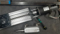
Figure 2. Lead screw drive system. Author’s image
Another source of linear motion is the spring. The more a spring is compressed or extended, the more force it will exert. This is called the ‘spring constant’, and it relates extension to force, such as pounds per inch, or kg per mm.
Hydraulic Forces
This section may as well be called ‘fluid forces’ but hydraulic systems are more likely to be used in the case of heavy loads. Air-powered pneumatic cylinders are commonplace, but the compressibility of air makes them less desirable when a cylinder must move to a position, then hold steady and resist pushback from the load. However, the physics of pressure are the same between both systems.
This pressure is responsible for generating a force, but it is not fixed. Just like the motors, where a radius may affect the amount of force, the same is true in hydraulic cylinders.
Hydraulic Linear
For linear motion, the internals of a cylinder consist of a piston with a round surface area constrained inside a hollow tube. When pressure is applied (again, hydraulic or air) the pressure is distributed over the surface area of the piston. If we want more force, there are two options, we can either increase the pressure, or we can increase the internal diameter of the piston in the cylinder.

Figure 3. Two methods of increasing the force on a fluid cylinder.
If you have a big enough piston, you can move some pretty incredible loads just with low to moderate system pressure. If you ever get to look inside a mechanic’s shop, large in-ground lift cylinders can elevate cars and trucks with ease.
Hydraulic Rotation
Hydraulic motors are an interesting innovation allowing fluid flow to drive a motor with a large amount of strength.

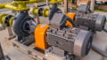
Figure 4. A hydraulic motor on an agricultural application. Author’s image
Inside a hydraulic motor is a set of small, spring-loaded pistons. These pistons are filled with pressurized fluid, one at a time, and press against an angled swashplate. The higher the angle, the more force from the fluid is transferred to rotation. Hydraulic motors are common in applications when hydraulic fluid is already used, but running wires for a single application might be difficult, such as with vehicles. Hydrostatic transmissions use the concept of hydraulic motors.
Summary
Creating force by converting energy is a creative process, being customized for every imaginable situation and machine. Surely this article doesn’t cover every possible source and variation of force delivery, but it does address the major ones.
If you’ve ever used a machine that delivered force in a creative way, be sure to share about it in the comments, and ‘May the 4th be With You’.


I can think of lots of applications but how force is delivered is basically as mentioned above. Now controlling force precisely is not covered. Different applications need different types of feedback. In lab environments a load cell iat the end effector is best as long as the amplifier is fast. In a mill a load cell normally as a half life of a few seconds. In this case NetForce=PressureA*AreaA-PressureB*AreaB. Of course this ignores seal friction but seal friction is usually small compared to normal operating forces.