
 Facebook
 Google
 GitHub
 Linkedin
Electricity and Electronics
Transformer Circuit Calculations
12 questions
-
Question 1 of 12
If an ‘isolation transformer’ (a transformer with the same number of turns in the primary and secondary coils) is connected between an AC source and an AC load, we will measure the same voltage and the same current at both source and load terminals:

If we calculate power output by the source and power dissipated by the load, the value is the same: 420 Watts ($P = I \cdot V$).
Now suppose we analyze a circuit containing a ‘step-up transformer’ (one with more turns of wire in the secondary coil than in the primary coil). With a step-up transformer, the load voltage will be greater than the supply voltage. In this example, I show a step-up transformer with a 1:2 step ratio:

Assuming the load resistance is completely different from the first (isolation transformer) circuit, what can you deduce about the load current and the power (both source and load) in this circuit? Is the load current less than the source current? Is the load current greater than the source current? Is the load power greater than the source power? Explain your answers.
Reveal answerThe basic physical law known as The Law of Conservation of Energy tells us that power cannot come from nowhere, or disappear into nowhere. If the power source is sending 420 watts into the transformer, then the load must be receiving 420 watts (neglecting any inefficiencies internal to the transformer). The transformer’s step ratio is completely irrelevant as far as power is concerned!
Notes:The only reason we might hesitate to that you can calculate load current precisely is because it doesn’t factor any losses fro mthe transformer. No real transformer is 100
The Conservation of Energy approach not only makes sense to students as they learn to calculate transformer behavior, but it is an excellent reinforcement of a basic physical law, a good understanding of which will serve them well throughout their careers.
-
Question 2 of 12
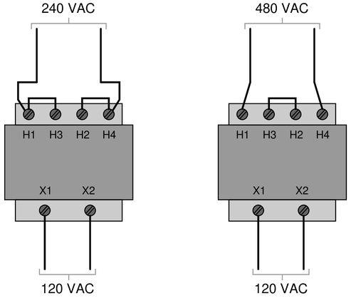
Industrial control power transformers are used to step down 480 or 240 volts to a level more acceptable for relay control circuitry: usually 120 volts. Some control power transformers are built with multiple primary windings, to facilitate connection to either a 480 volt or 240 volt AC power source:

Such transformers are usually advertised as having “240 $\times$ 480” primary windings, the “$\times$” symbol representing two independent windings with four connection points (H1 through H4).
Show the connections on the four “H” terminals necessary for 240 volt operation, and also for 480 volt operation, on the following illustrations:
 Reveal answer
If the coils are to be considered a resistors, since the same series/parallel equations apply to both, then we could consider how high and low voltage might affect resistors.
With a 240 volt supply, this (relatively) low voltage can be dropped across both inductors, and placing them in parallel provides more energy and less loss, while inducing a voltage on the secondary coil.
In the case of (relatively) high 480 volts, the coils placed in series will allow both coils to drop 240 volts, exactly the same as before. Therefore, in both cases, two coils are dropping 240 volts, and the resulting voltage on the secondary coil will be the same.
 Notes:
This type of transformer is very common in industrial control systems. Discuss with your students why the primary winding terminals are arranged as they are (H1-H3-H2-H4), to facilitate near-terminal jumpering with metal clips.
-
Question 3 of 12
Calculate all listed values for this transformer circuit:

{\bullet} $V_{primary} = $
{\bullet} $V_{secondary} = $
{\bullet} $I_{primary} = $
{\bullet} $I_{secondary} = $Explain whether this is a step-up, step-down, or isolation transformer, and also explain what distinguishes the “primary” winding from the “secondary” winding in any transformer.
Reveal answerTo begin, we immediately know the voltage applied to the primary coil from the basic information provided.
{\bullet} $V_{primary} = 48~volts$
To identify the secondary voltage, the turns ratio of the transformer is 13000:4000, so the secondary will be lower voltage by a 13:4 ratio.
$${V_{primary} \over V_{secondary}} = {13 \over 4}$$
{\bullet} $V_{secondary} = 14.77~volts$The secondary current is the next simple calculation, based on Ohm’s Law:
$$I_{secondary}={V_{secondary} \over R_{secondary}}$$
{\bullet} $I_{secondary} = 98.5~mA$Finally, the current in the primary is found be either letting the power (V x I) of the secondary equal the power of the primary, or use the same turns ratio equations for voltage, but reverse the ratio, as current and turns re inversely proportional.
{\bullet} $I_{primary} = 30.3~mA$This is a step-down transformer.
The primary winding is connected to the source. There is no limitation on which side should have more or less windings, so it is unwise to assume that the higher turns indicate the primary side.
Notes:Most transformer problems are nothing more than ratios, but some students find ratios difficult to handle. Questions such as this are great for having students come up to the board in the front of the classroom and demonstrating how they obtained the results.



It will be very useful if you show the formulas or how you got the answers. Thank you